Utility Locates
Image 1 of 31
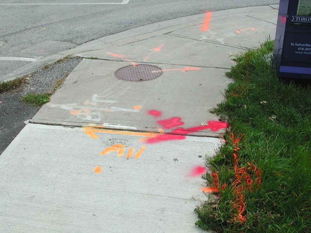
You've seen lines spray painted on the roads and sidewalk. Here were going to talk a bit about utilties, such as buried natural gas and water pipes, and electricity and communication cables.
Image 2 of 31
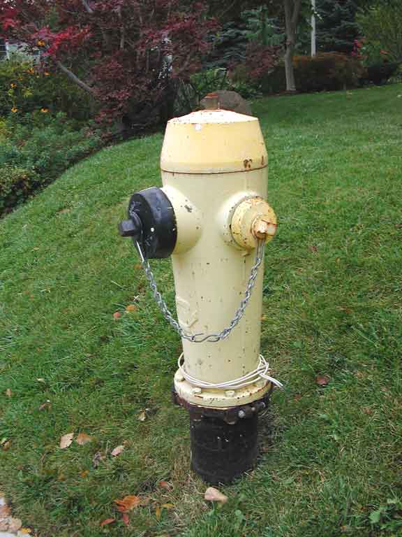
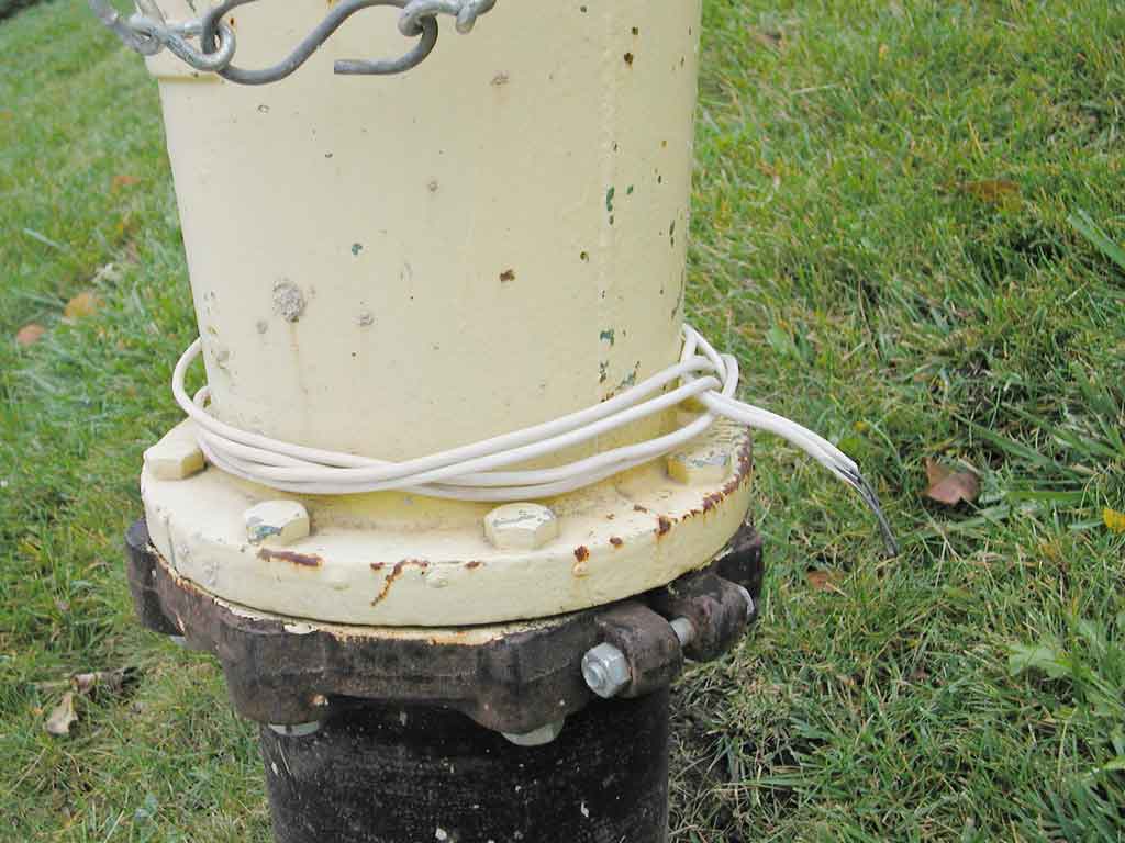
Here is a fire hydrant. You may notice that there's a wire wrapped around the base.
Image 3 of 31
Most recently installed fire hydrants will have a nearby wire coming out of the ground (and the extra slack is wrapped around the hydrant). There's an interesting story behind this (well, I think it's interesting).
Image 4 of 31
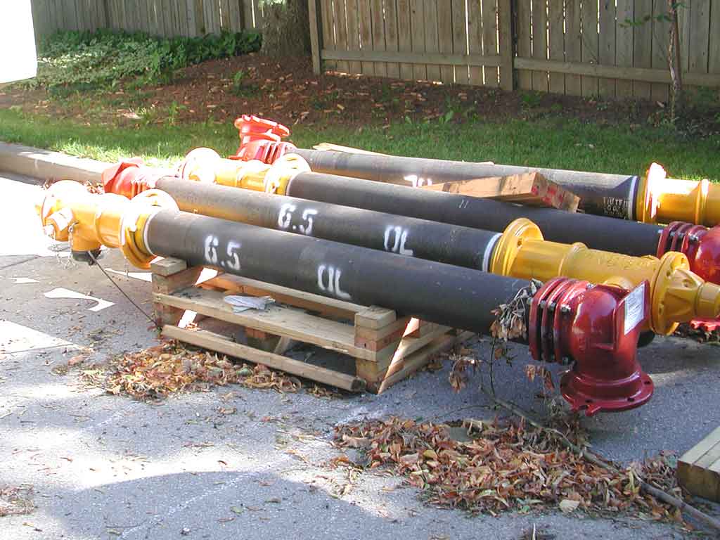
The nozzle section of this hydrant has one pumper nozzle (the larger one) and two hose nozzles. As shown in the datasheet here, this is a dry barrel hydrant, where the valve is in the base (at the very bottom – so normally, the water isn't in the hydrant or lower barrel). The main advantage of this is that the water won't freeze in the winter, since it is all below grade, where the water main is. In fact, there's usually a small hole in the base of the barrel, so if the valve does leak, the barrel won't fill with water, freeze in the winter, and therefore possibly not gush water when needed. The other advantage of a dry hydrant is that if a car knocks the whole thing over, you won't get a geyser of water, since the shut-off valve is 6' below grade. In fact, the flange at the top of the lower barrel is specifically designed to break (before the rest of the hydrant), so the $2,000, 500-pound hydrant (hopefully) isn't damaged. The datasheet for the $150 flange repair kit is here.
Image 5 of 31
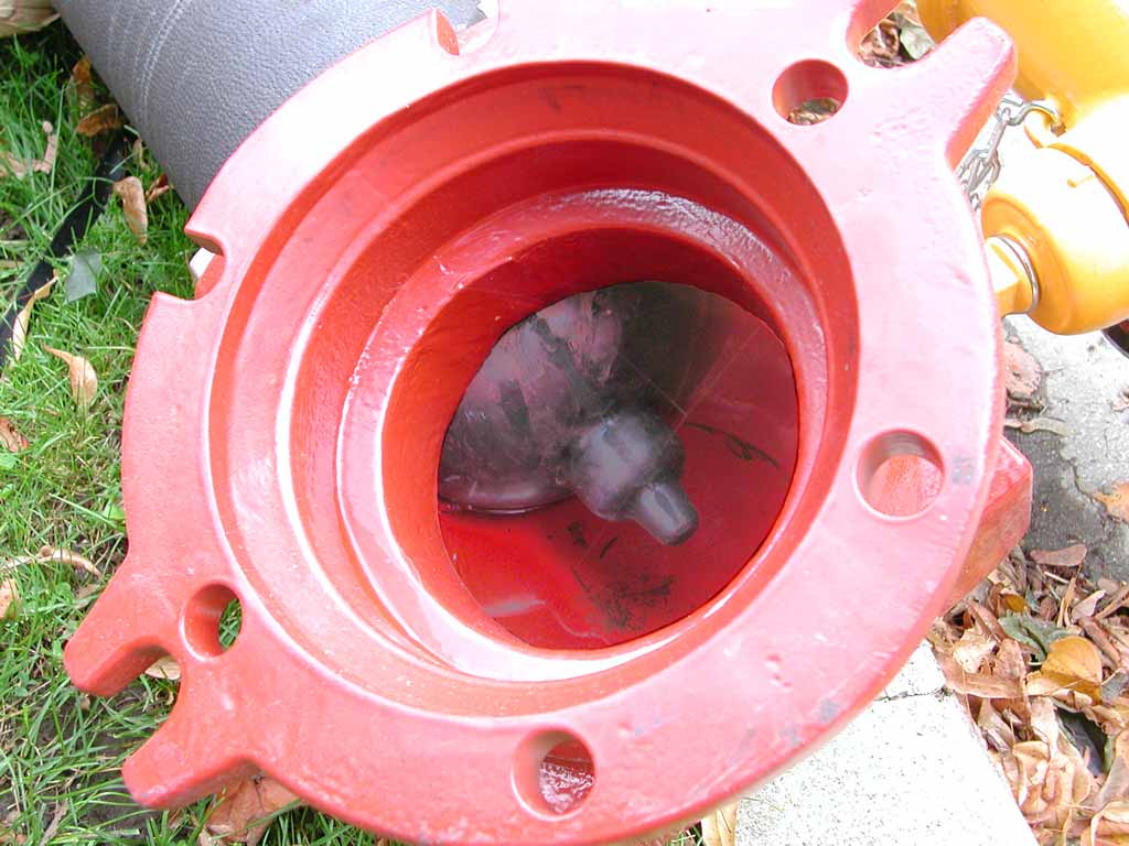
Image 6 of 31
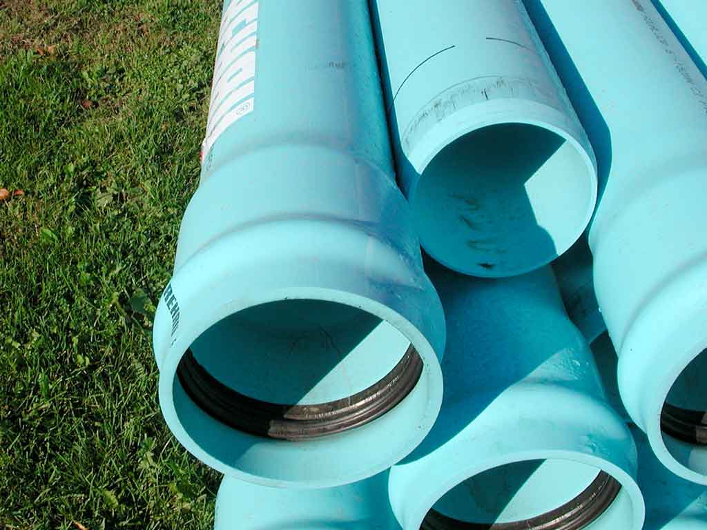
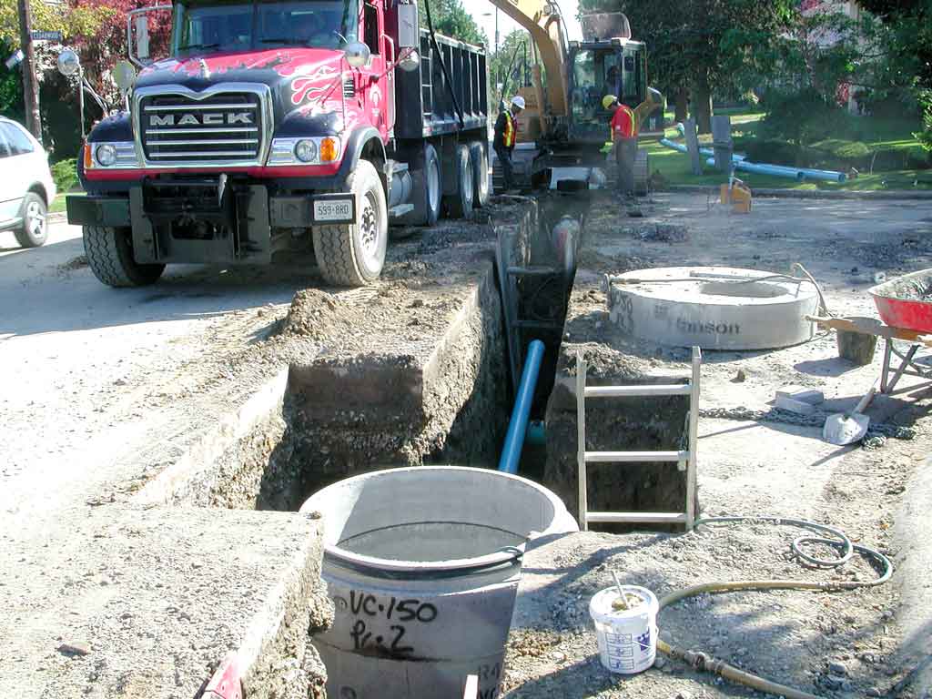
Here's the plastic water main pipe used to supply water to both your home (through a smaller supply line) and fire hydrants. This particular pipe is AQUALOC Municipal PVC Pressure Pipe, type DR18 (which indicates the maximum pressure for which it is designed). It is 150 mm in diameter, and made of polyvinyl chloride. The brochure for this pipe is
here, and the manufacturer's technical manual is here.
You can see that the spigot end of the pipe has been bevelled, and the bell end has a larger diameter, with a black rubber “O” sealing ring in it. The bevelled end is pushed into the O-ring end (up to the black mark).
Image 7 of 31
Here the water pipe is being buried, to replace the iron pipe that has been installed for the past 40 years (the water pipe is left buried, and are occasionally then used for other purposes, such as conduits for fibre optic cables).
The lid of the concrete valve chamber has a round opening, above which a cast-iron man hole will be installed, the top surface of it will be flush with the pavement.
Image 8 of 31
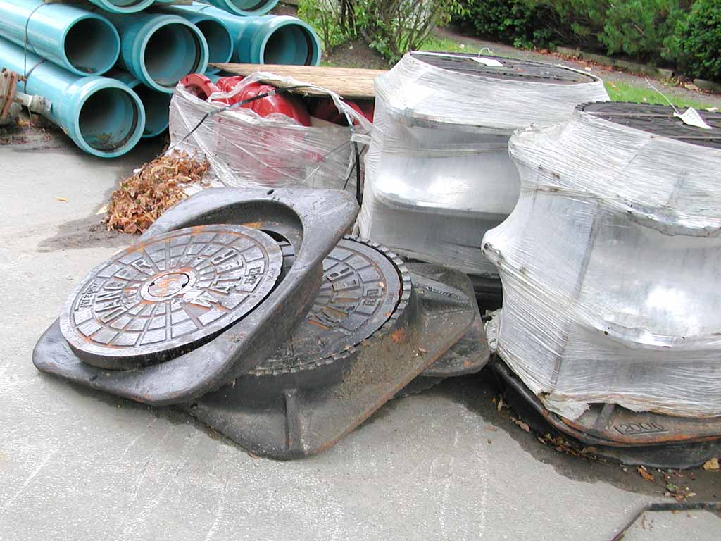
Here are the man hole covers (also called access covers) waiting to be installed. They consist of the round cover (round, as square ones would be able to fall into the hole) and the frame (also called a ring). The bottom one on the left is as you'd normally see it (though the base of the frame would be below the road surface). The one above it has the frame upside-down.
Image 9 of 31
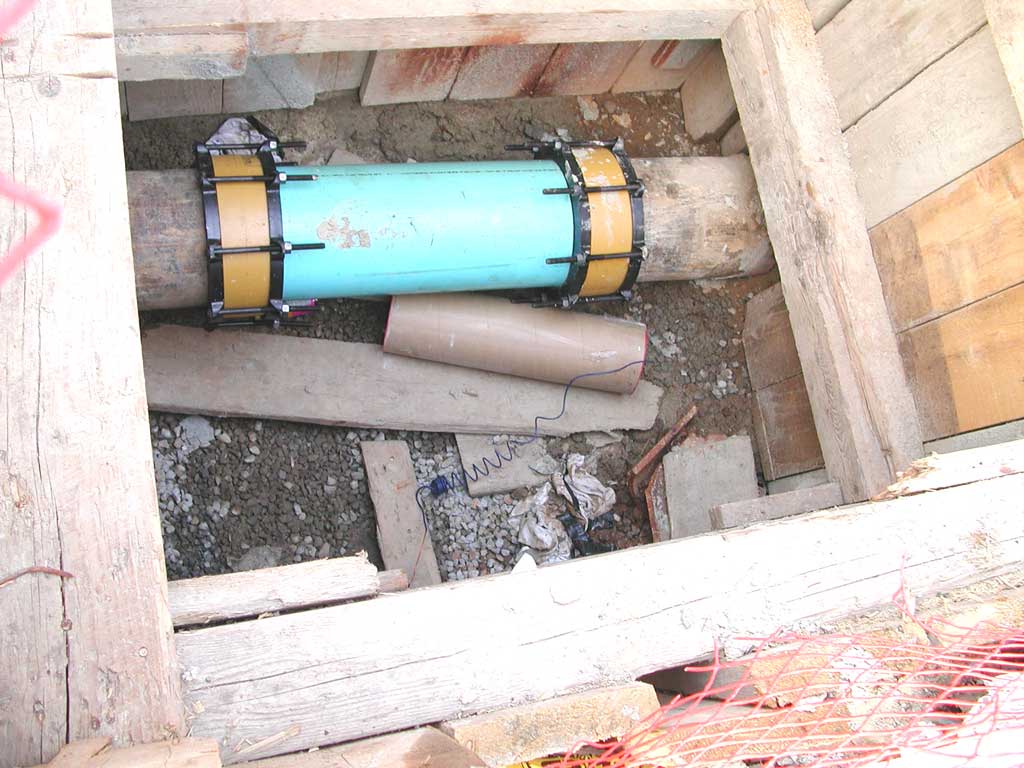
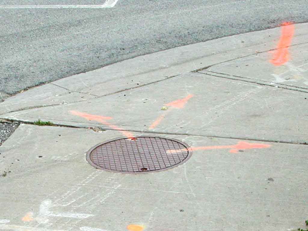
Here we're looking down an excavation at a 12" water main being rehabilitated.
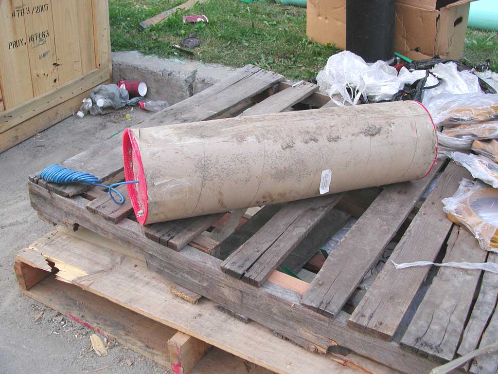
Municipalities do many things to prolong the life of iron water pipes. Sometimes they are lined with a polymer to reduce corrosion, but here is a new plastic section of water main spliced into an existing (old) cast iron water pipe. Let's talk about that the big cardboard tube with the blue wire spiral (which will soon be welded to the iron pipe).
Image 10 of 31
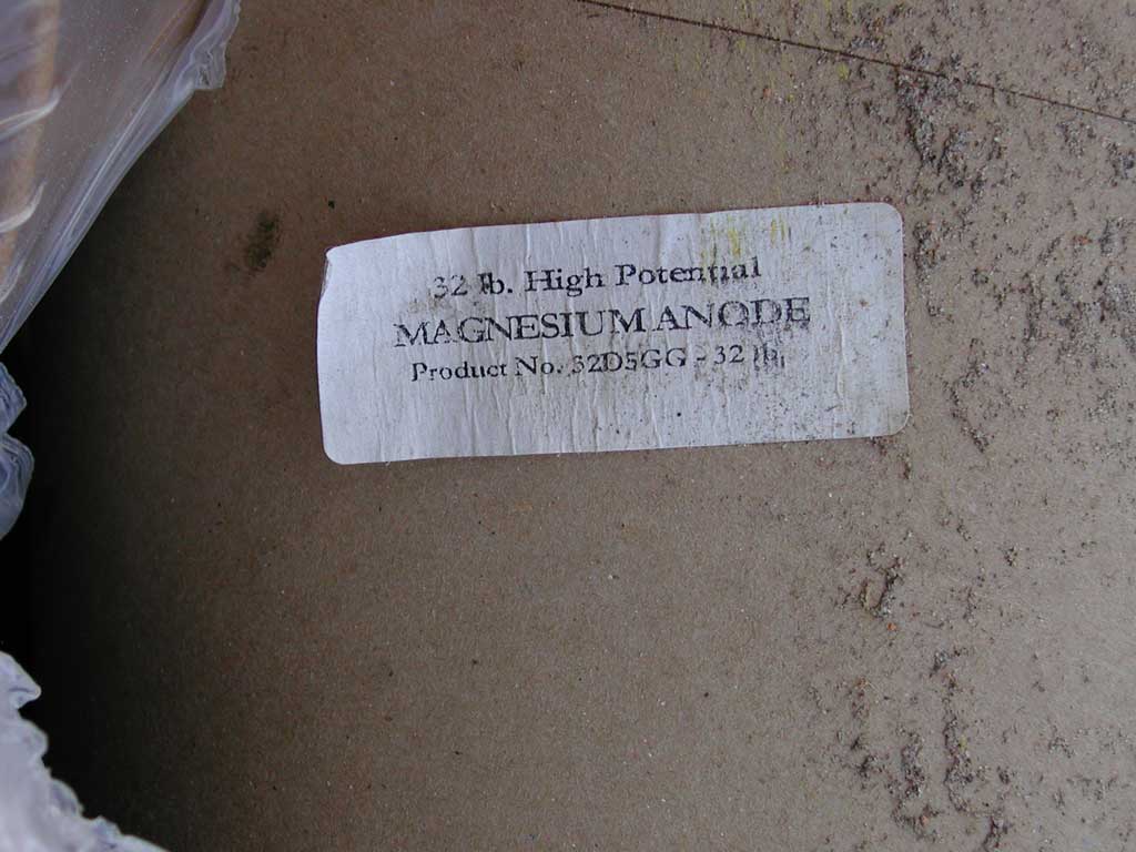
Here's a close look at the sticker on the side. This is a 32-pound, high-potential magnesium anode, model 32D5GG-32lb.
Image 11 of 31
Here's a nice view of just the cardboard tube, which is an outer cover for a sacraficial anode, made by Corrosion Service Company Ltd.
While most metals corrode (that is, they rust), some like to corrode more than others, and this is due to the potential (voltage) formed when metals are in contact with an electrolyte (which allows ions to migrate from one metal to the other). The galvanic series (or electropotential series) below shows for galvanic corrosion, which metal will corrode (the one farther down the list becomes the anode, which loses ions) to protect the other (which therefore benefits from cathodic protection).
- Platinum
- Gold
- Silver
- Stainless steel (the exact position in this list depends on its composition)
- Brass
- Chrome
- Copper
- Cast iron
- Steel
- Lead
- Tin
- Aluminum
- Zinc
- Magnesium
Note that compared to all the other metals listed, magnesium is corroded, and the other metal is therefore protected. A block of magnesium therefore becomes a sacrificial anode when it is electrically attached to a metal lower in the series (such as a water pipe, which you really don't want to rust).
The data sheet here shows that there is a 32 pound block of magnesium in this cardboard tube. The rest of this tube is filled with powdered Wyoming Bentonite and other great things to keep the magnesium block in good electrical contact with the soil. The blue wire is electrically connected to the magnesium block inside the cardboard tube, and the wire is attached to the water pipe, which then receives the cathodic protection.
Image 12 of 31
Before digging or excavating, contractors and homeowners must request a utility locate to ensure that they won't damage buried pipes and cables. But when a pipe or cable is buried, how can they be located without first digging? (that was a rhetorical question).
While as-built drawings and other documentation should indicate approximately where everything is below grade, the most reliable way to determine what is buried is to use an electronic device to detect exactly where everything is (though there are credible reports of divining rods and sticks being sucessfully used).
Since it is important that utility locates be done quickly (since construction needs to be scheduled in advance), and since all utilities (gas, water, sewer, electricity, cable TV, telephone, and possibly others) need to locate their services, the utilities in many areas support a central service that performs all the locates for all of them, at the same time. Examples are Ontario One Call, Miss Utility, Dig Safe. Typically, these organizations are somewhat like call centres, and subcontract out the actual locating, to an organization such as this.
When a locate is done, coloured spray paint is used for the markings, which are either:
- A line with arrows, indicating the path of the buried cable or pipe.
- Two parallel lines, indicating the width of the trench in which the cables, pipe, or duct (generally white or grey 3" or 4" diameter plastic pipe, which may be encased in concrete) are installed.
As described here, the colour code used for the spray painted markings are usually as follows:
- Red: Power lines. Many areas currently use 27,000 volt power distribution to the transformers which are pole-mounted or below grade in transformer vaults. So accidentally digging into one of these would be a very bad thing. Generally an “H” is spray painted alongside the red line, to indicate Hydro (as in hydro-electric power – which is how most electrical power was generated before nuclear power became more common).
- Yellow: Usually indicates natural gas, such as that which heats most people's homes and water, but can also indicate an oil or steam line. A “GM” indicates the gas main running down a street, and a “GS” indicates the gas service running from the gas main to a house or business.
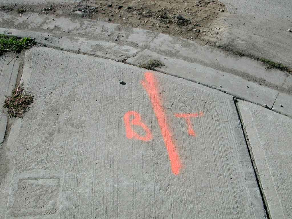
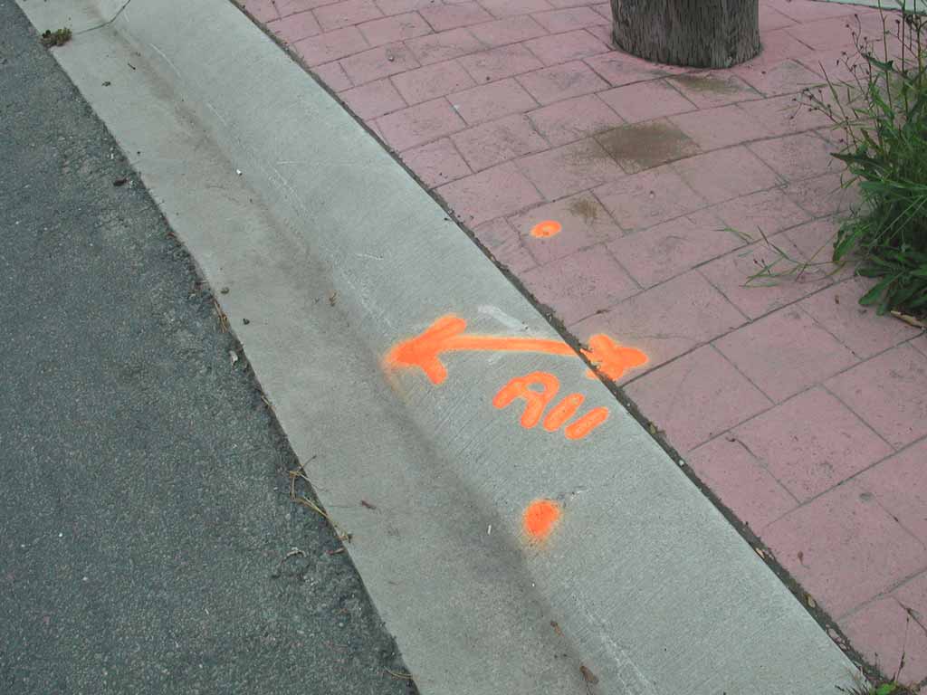
- Orange: Communication cables, such as telephone lines and trunks, cable TV coaxial cable, and fibre optic cables. “BT” indicates telephone (as in Bell Telephone), TV indicates a cable television coaxial cable or fibre optic cable and a “FO” indicates a fibre optic cable. Traffic signal cables are also often marked with orange paint, sometimes with the letter “T”.
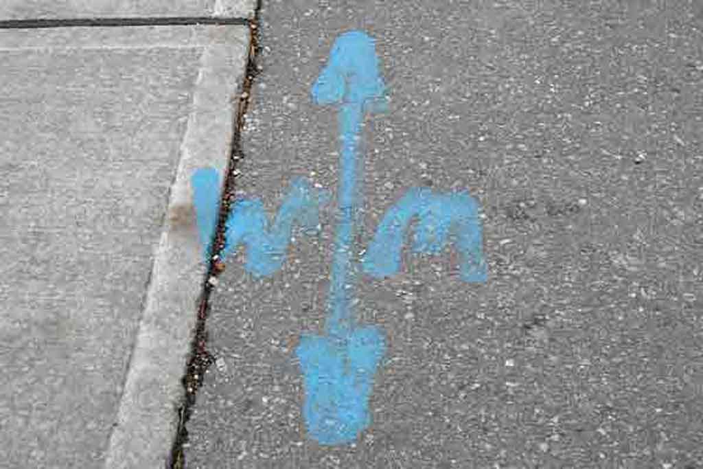
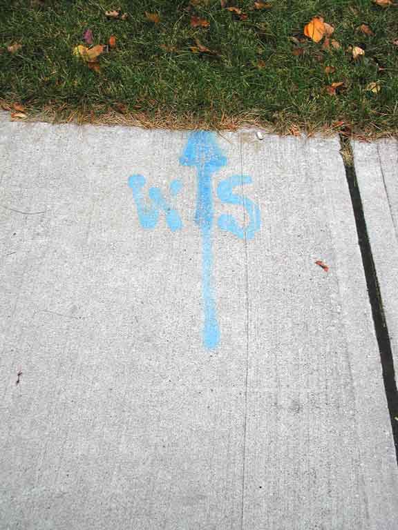
- Blue: Indicates water, most often the water supply to people's homes (often called potable water). A “WM” indicates a water main running down a street (often 6" or 10" diameter), and a “WS” or “S” indicates the water supply line (often a ¾" or 1" copper pipe) running from the water main to a house or business.
- Green: Indicates a sanitary sewer (that usually eventually goes to a water treatment plant) or storm sewer (that typically goes to the nearest stream or river). These will typically be marked by an “SS” or “S” (which doesn't quite differentiate the two).
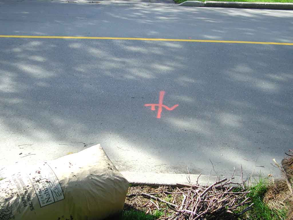
- Pink: Survey markings, for example, to either indicate property boundaries, or to match markings on drawings for road or sidewalk construction. The marking is often an “X”, where the centre indicates the exact survey point (often along with a narrow and shallow saw cut).
- White: Proposed excavation markings, such as where saw cuts are to be made in the asphalt for a road repair or to dig up a pipe.
So, in the picture, there's a buried water main underground (note the “WM” is a 180° rotational ambigram of itself).
Finally, the reason for the wire. Except for fancy ground penetrating radar devices (such as this), subsurface locating systems rely on the buried cable or pipe being metalic, for example to:
- Disturb an electric field generated by the locating device.
- Conduct a signal injected by a transmitter. This transmitter is usually part of the locating system, and may be:
- Electrically attached to the cable or pipe (another wire from the transmitter will be grounded, usually through a stake driven into the earth). By attaching the transmitter to the pipe, one can be sure that the desired pipe is being followed.
- Inductively coupled to it either by placing the transmitter parallel (and as close as possible, for example, directly over the expected location) to the cable or pipe, or by clamping a coil around the conductor or pipe.
- Carry the power for which the cable was installed. That is, the locating device senses the 60 Hz frequency from a power line.
- Carry a signal associated with the cable. Amazingly (read about it here), the 31.5 kHz second harmonic of the NTSC television horizontal scan frequency is coupled onto the cable TV coaxial cable by the yoke coils of an operating television receiver, and this can be used to locate buried coaxial cable.
Brochures on locating devices are here and here (the whole manual for that one is here).
So, the wire at the base of recently-installed fire hydrants is a tracer wire, and contractors are required to lay these in the trench, above plastic water mains, solely for the purpose of later locating the exact path of the buried water main.
Finally finally, there is the issue of how deep is the buried pipe.
- While the signal strength from the transmitter is a rough indication, locators typically will open man-holes and valve chambers and measure the distance down to the pipe using a tape measure. By doing this at each end of the pipe, the depth at points between these can be estimated through interpolation.
- Some locating systems have a device (which may be called a beacon or a sond ) which can be pushed into the pipe using a fibreglass rod, and the locating device measures the received signal at its receiving antenna close to the ground and another antenna farther up the locating device, closer to the operator. The distance to the beacon can then be determined by the time difference of the received signals.
Image 13 of 31
Being orange, this indicates a communication cable, and the “BT&rdquo indicates it is a Bell Telephone cable (either copper or fibre optic).
Image 14 of 31
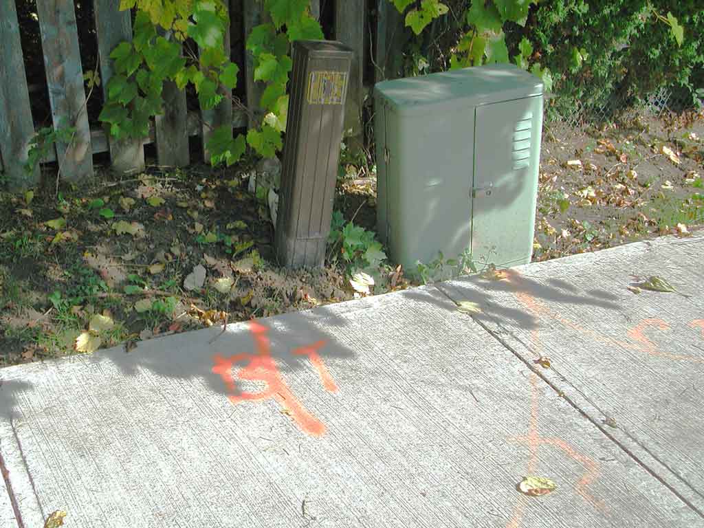
Often you can identify who owns pedestals by the markings. Both of these are telephone company splice cabinets.
Image 15 of 31
This marks a buried fibre optic cable, owned by Allstream.
Image 16 of 31
Here is a buried cable TV coaxial cable. It is very neatly marked.
Image 17 of 31
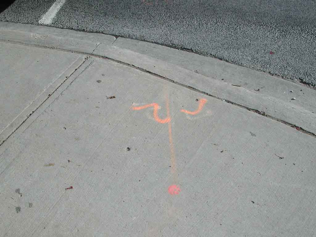
Sometimes the guy doing the locate doesn't make perfect letters. Often the markings are over ealier, faded, markings.
Image 18 of 31
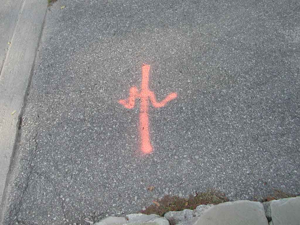
Sometimes you have to know what the letters should say to read them (there's a bit of hand-eye coordination needed for the moving of the hand, and pressing of the top of the can of spray-paint).
Image 19 of 31
This is a traffic signal hand pull. It is a small cable vault into which run the conduits with cables that provide power to the traffic signal lights, and receive input from pedestrian cross request push-buttons and inductive loops that are connected to traffic detectors.
Image 20 of 31
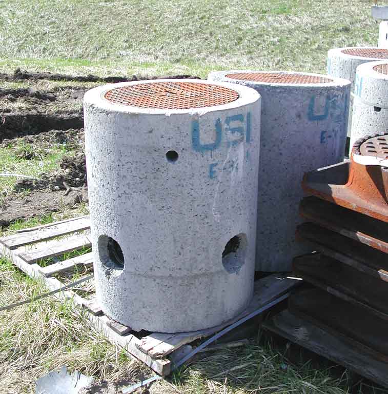
This small cable vault is likely larger than the hand-pull used for the traffic signal cables above. When installed, the top is flush with the sidewalk. The concrete section below has holes for the conduits, and is large enough for cables to be pulled through, and fed into other conduits.
Image 21 of 31
Here is the water service going into someone's house (so you'd expect it to be at right-angles to the sidewalk, as it is). The water main in the previous picture ran along the road (and sidewalk), again, as you'd expect.
Image 22 of 31
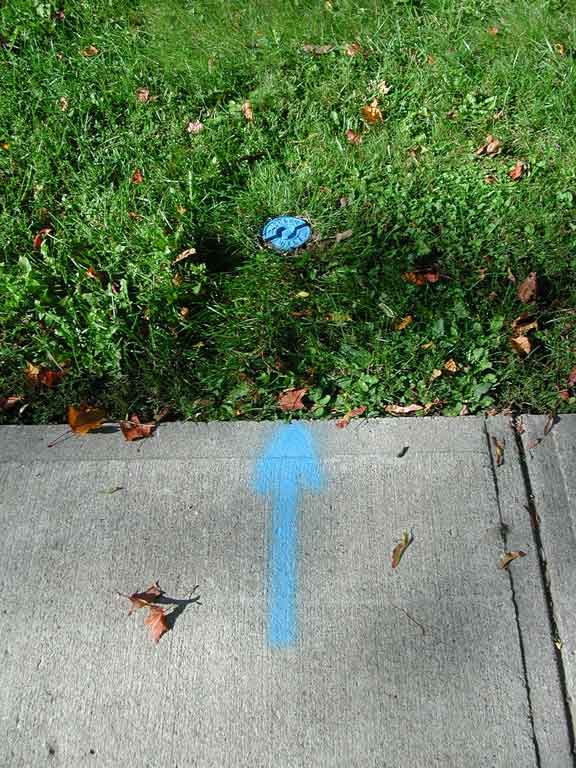
Here (again in blue) is a marking for the water service. While there's no “WS” spray painted (there was a line like this along the sidewalk for every house on the street, so this was much less of a mess), it does point to the curb stop (also called a shut off, and anyone who cares will understand what it is anyways), which is the blue round thing (you often see these flush with the pavement in people's driveways). It has a cap in the centre (to prevent sand falling in) which can be unscrewed. The hole leads to a vertical pipe through which a long wrench with a “T-shaped” handle can be inserted, to turn off the valve which is in-line with the water service pipe (which will always be below the frost line, typically 4' to 6' down). This is used by the local municipality to shut off the water to the entire house.
Image 23 of 31
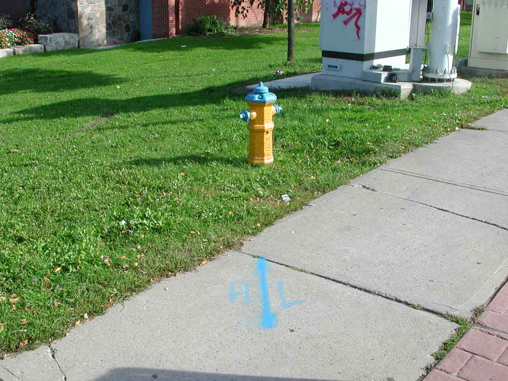
I suppose “HL” means hydrant line.
Image 24 of 31
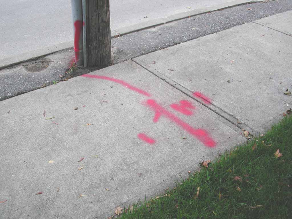
This red paint marks a buried power line (note the “H”, for Hydro). The power line is run down the utility pole (protected by heavy-gauge galvanized sheet metal), and beneath the sidewalk to a house. Note how the red marking runs up the utility pole to identify exactly where the cable goes.
Image 25 of 31
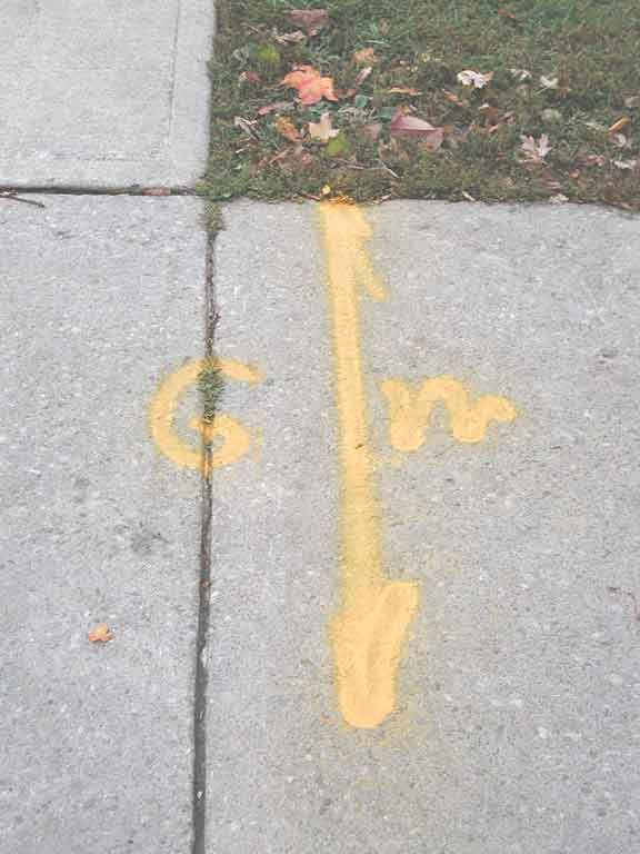
Being yellow, this is a gas line, and the letters indicate it is a gas main.
Image 26 of 31
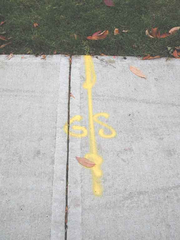
Here is the gas service to someone's home, again, at right angles to the sidewalk.
Image 27 of 31
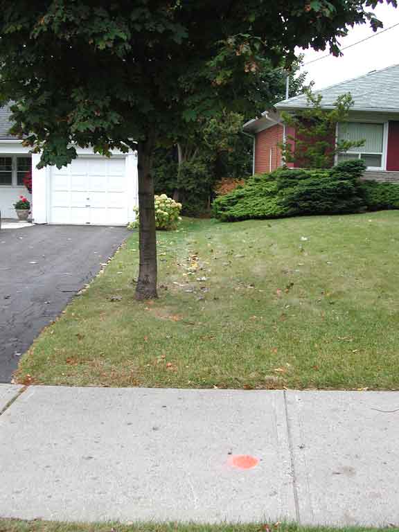
Here is an orange dot, somewhat in-line between the two houses.
Image 28 of 31
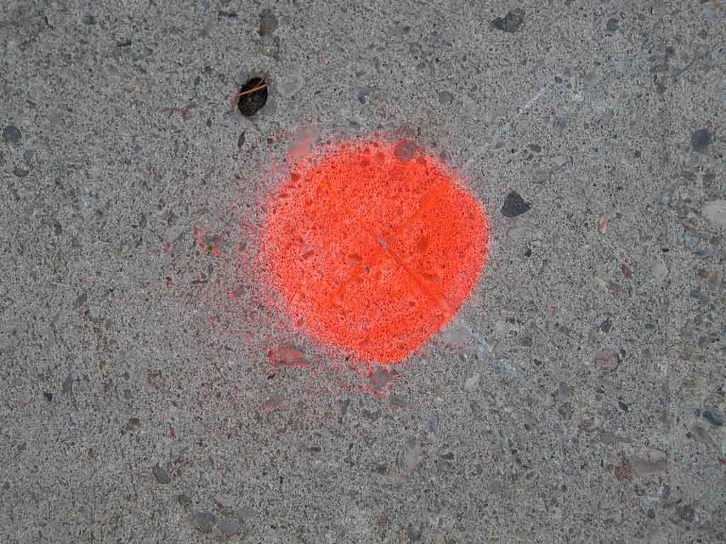
Looking closer, we can see a surveyor's cross-cut. Here it marks the property line between the two houses.
Often this will be done when a house is purchased (the mortgage company generally requests a survey of the property, and if one is not available, a surveyor must be requested to locate the property boundaries).
Image 29 of 31
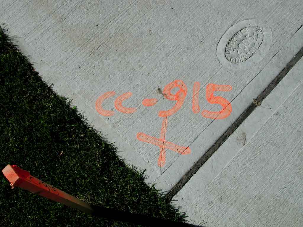
Here is another surveyor's cross-cut, but in this case there is a designation (which matches that on the nearby wooden stake). This will generally match a corresponding designation on a scale drawing of road or curb work to be done.
Sometimes the markings will indicate an offset from what is really of interest. For example, the distance to the crown (centre) of a road to be rebuilt will be indicated – you can't put the markings directly on the road, since they would be covered-up by the road work, so a point (for example) exactly 3 meters away will be marked, with a designation such as “+3.00” along with an arrow.
Image 30 of 31
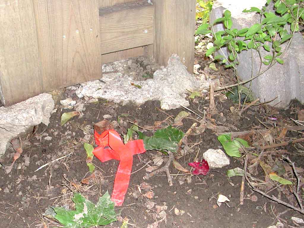
This is a surveyor's iron bar. It is typically ¾ square, and driven into the ground to mark the corner of a property. Here, an orange fluorescent plastic tape is tied around it so it is easier to find.
Image 31 of 31
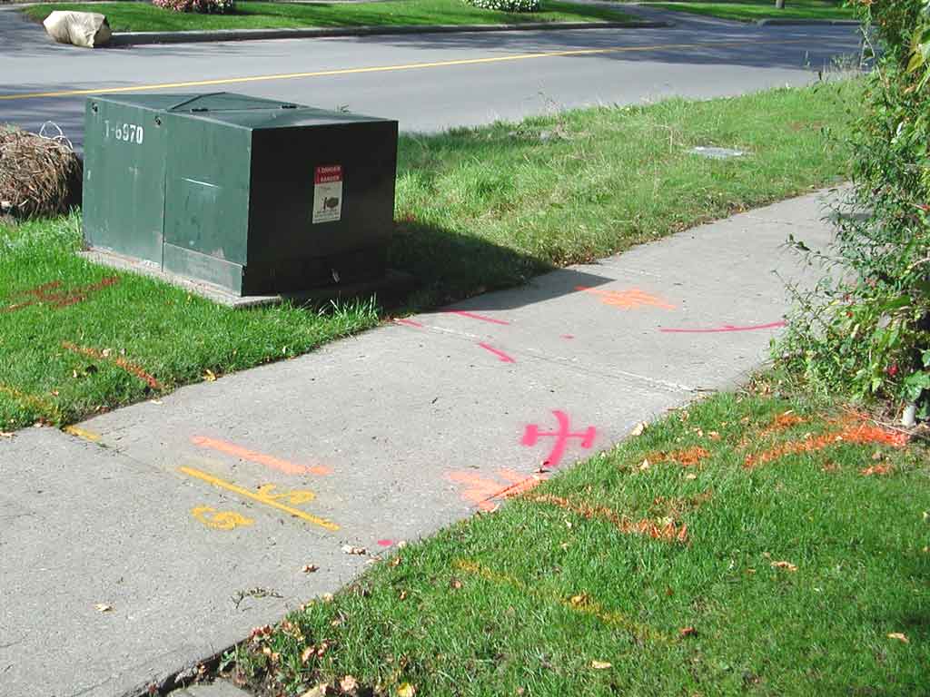
So here is a surface-mounted 27,000-volt distribution transformer (in dark green cabinet). It is fed by a buried power line that runs parallel to the sidewalk and road, under the boulevard (the strip of grass between the sidewalk and road). The transformer's 110/220 volt output goes to nearby houses. There is a buried natural gas supply line running across the sidewalk, close to the cable TV coax.
