A 3,600-pair Cable Pull
1 of 21
Ah, what have we here. A huge reel of something on a trailer, being pulled into an underground cable vault.
It turns out this is a 3,600-pair (that is, enough to support 3,600 houses, each with their own telephone line) telephone feeder cable being installed for the telephone company. This steel reel (which will be returned to the factory to be reused) holds up to 1,000 feet of cable. The cable is being pulled to the next cable vault up the street (just under 1,000' away).
The diagram here shows the names for the cables between a telephone company central office, cable vault, front-yard pedestal, and finally, the service or drop cable into people's homes.
2 of 21
And here is the next cable vault. This truck has a winch which is pulling the cable (with a huge amount of tension, as it turns out the 4" conduit between the two vaults has several bends in it, which greatly increases the pulling force required).
The conduit (which is also called a cable duct) is installed in a trench, along with other conduits, each separated by plastic spacers. Then concrete is poured into the trench to protect the conduit from subsequent digging, animals and other hazards.
But what is pulling the cable through the conduit.
3 of 21
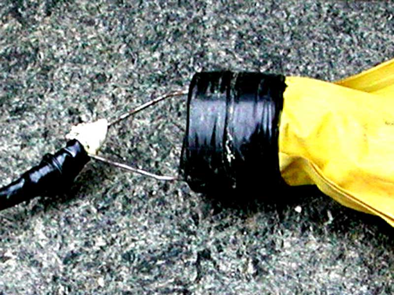
This makes for a story. The conduit has recently been installed, and there is nothing in it. They need to end up with a heavy steel cable in the conduit, to pull the 3,600-pair cable through. But it all starts with this. It is called a balloon, and is frirst put into the conduit, with a rope, tape, or string tied to the wire loop.
4 of 21
Here's a close-up of the wire loop. The end of the balloon is held open with a cylinder (under the black vinyl electrical tape).
5 of 21
Yellow polypropylene rope or blue and white polypropylene twine is often used to pull cables through conduits, but this is called Mule-Line or Bull-Line. This particular stuff is made by Arnco Corporation. Click here for the data sheet and here for a brochure. This tape has an 1,800-pound pulling strength, and installers like it more than rope because it is very slippery so if you're pulling the tape through a conduit which already has other cables in it, the other cables won't be damaged.
Another problem with using the more-traditional polypropylene rope or twine is that friction causes it to heat up as it is pulled, and when pulling stops, it might melt to the conduit and get stuck.
The brochure gives instructions on tying the best knot (a "double-ply retraced overhand", which they call a Bull-Knot), and the relative strength of the Bull-Knot, a standard square (or reef knot, which is the worst) and a bowline knot.
6 of 21
And here's the end doing the pulling.
First, though let's talk about the portable air compressor (the yellow trailer). It is an Atlas Copco XAS96 with a diesel engine of about 45 horsepower and generates about 100 pound/in² air pressure (standard for vitually all air-powered tools, from the hoists at General Motors' assembly plants to the jack-hammers used for road repair). Here, the air pressure is used to blow the balloon (with attached pull-tape) through the conduit.
When the other end gets the pull-tape, they attached the steel cable from the truck's winch and the steel cable is pulled back through the conduit, which is then attached to the end of the 3,600-pair cable, and the truck's winch pulls it back through the conduit.
Here are a few interesting points:
- When the pull-tape is blown through the conduit, it may run into an obstruction. Another advantage of using the pull-tape, rather than a rope or string, is that printing on the pull-tape indicates the distance. By noting the distance mark before the pull-tape is blown into the conduit, and the distance mark when the pull-tape runs into the obstruction, the crew can know how far the obstruction is into the conduit, so they know where along the path to dig to fix it.
- If the cable to be pulled is light-weight (such as a fibre-optic cable, or a low pair-count copper cable), then the pull-tape itself can be used to pull the cable through the conduit (no need for the steel cable), especially if more than one run of pull-tape is used.
- Atlas Copco sells 30% of all construction air compressors world-wide. Some information on their current portable air compressors is here. The model in the picture is similar to the one here.
- Some information on Atlas Copco's "rotary screw" method of compressing air is here.
7 of 21
Here's the inside of the contractor's truck at the pulling end. I suspect the microwave oven in there is for their coffee breaks, nor for anything fancy like curing cable splices.
8 of 21
But below and to the left of the microwave oven are some umbrella-looking things. These are sometimes called darts, and are another design used to be blown through a conduit to get a pull-tape, string, or rope from one end to the other.
9 of 21
You've seen a back-hoe before, but perhaps wondered (or maybe not!) about the big pulley attached to the hub of the wheel. This is used as a winch to pull cable through conduits. They use the back-hoe's hydraulic outrigger to lift the wheel off the ground, and run the engine to turn the wheel.
They could wind the pull-tape onto the pulley to pull the steel cable back through the conduit, but then they'd have to unwrap the pull-tape off the pulley later. So instead they just wrap the pull-tape around the pulley two or three times, and by hand, keep tension on the pull-tape as it unwinds off the pulley, while it pulls the steel cable through the conduit.
10 of 21
They don't reuse the rope or Bull-Line. Even if they could keep it from tangling, if it ever broke, it would be really bad, as they'd have to pull the cable back out from the reel-end, and there's no easy way to do that.
Still, it is a shame that all this gets thown into the garbage after being used only once.
11 of 21
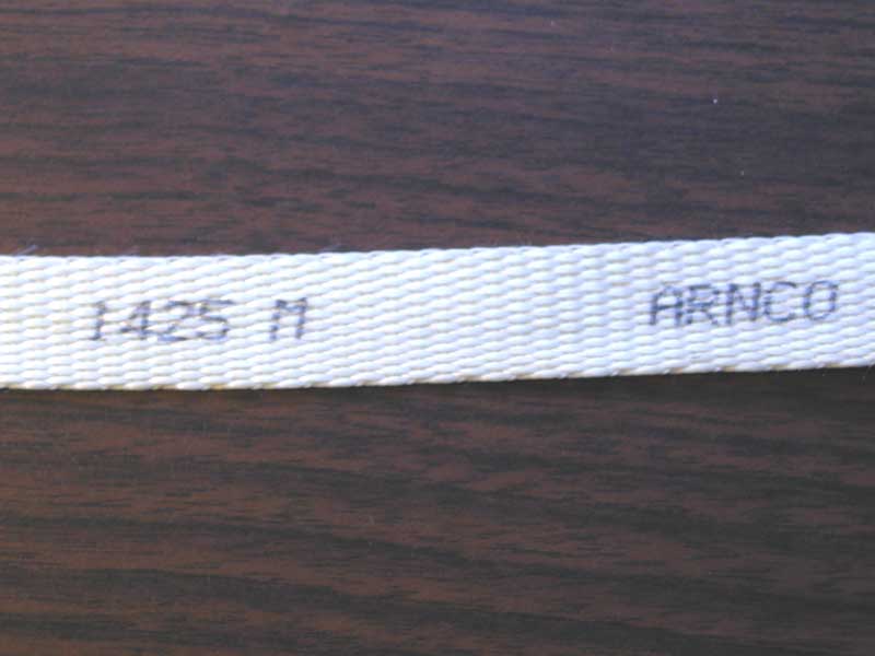
Here's the Bull-Line up close. "WP1800" indicates it is woven polyester, with an 1,800-pound pulling strength.
12 of 21
This distance marker shows the 1,425 metre mark.
13 of 21
The winch truck has a hydraulically-operated boom with large pulleys. They want to pull the cable straight through the conduit, so a second pulley at the bottom of the boom is in the cable vault.
14 of 21
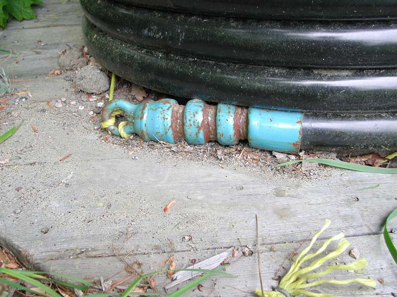
This is a different cable reel, but it shows the pulling loop on the end.
15 of 21
To keep the cable from being damaged from the sharp corners before it gets to the underground conduit, an armoured guide is used. The yellow polypropylene rope tied around the end keeps it from falling into the cable vault.
To reduce the friction of pulling the cable through the conduit, a "cable pulling lubricant" is used (from the five-gallon pail to the left). The funnel at the top is called a collar, and helps to get most of the stuff into the guide.
16 of 21
Here is PT Technologies' summer grade (this is water-based, so would freeze in the winter) TechLube-HD. More information is here.
17 of 21
Here's a close-up of the 3,600-pair cable. It is made by General Cable Technologies Corporation, who have information on their Telecommunication Cables here.
A data sheet on this DCTZ-3600 cable is here. It shows that:
- This is 26-gauge cable, which is thinner than the 24-gauge usually used by telephone companies. This enables them to get more pairs into the 4"-diameter conduit. In fact, this entire line of cables are designed "for use in urban underground ducts where duct congestion is a prime concern" (there's never enough room in underground cable ducts).
- The 1,000' length of cable on this spool weighs over 7,000 pounds (more than a minivan).
- The cable is shipped under pressure (and the ends tightly sealed to maintain the air pressure). This ensures that if there is a small hole in the cable jacket, the air will come out, rather than any moisture getting in.
- One of the few technical specifications on the data sheet notes that the attenuation is measured in dB/kft at 772 kHz.
- Firstly, attenuation (how much the signal gets "quieter") is measured in decibels (named after Alexander Graham Bell himself), and a "Bel" turns out to be too large for most purposes, so a tenth of a Bel is used instead, which is a deciBel.
- "kft" is a kilo-foot (1,000'), and is the traditional distance measurement in the telephone industry (that would be 304.8 metres).
- Finally, the frequency of 772 kHz is exactly half of 1.544 MHz, and the bit-rate for a T1 circuit is 1.544 Mbits/s. T1 circuits are very common in the telephone industry (they can carry 24 64-kbit/s digitized voice channels), and due to the modulation method used, the frequency when T1 data is sent is half of the bit-rate. The attenuation at this particular frequency is therefore of interest (to telephony engineers anyways).
A catalogue page is here. It notes more about the construction of the cable.
18 of 21

- Solid (rather than stranded, where there are several smaller gauge conductors) copper conductors (copper is used because it has low electrical resistance, and is flexible and low-cost. The conductors are 26 AWG. AWG is an abbreviation American Wire Gauge, more commonly simply called gauge, which is the traditional way to measure conductor diameters. 26-gauge has a diameter of 0.404 mm (24-gauge conductors have a diameter of 0.511 mm).
- Each conductor is insulated with a two-layer insulation. The inner layer is foamed, as the air bubbles give better electrical properties (they reduce the dielectric constant of the insulation, and therefore reduce the capacitance between pairs, and this reduces the cable's attenuation of higher frequencies). This layer is covered by a non-foamed (solid) plastic, as this won't absorb water (which is really bad for electrical conductors, for example, it is one cause of cross-talk, where you hear other people's conversations), and is not as fragile. This two-layer design reduces insulation thickness, so makes the entire cable thinner.
- Pairs of insulated wires are twisted to each other. A standard colour code (which is here) is used so technicians can identify each pair of conductors. For example, the blue wire with the white stripe is twisted to the white wire with the blue stripe. The twist pitch (which is the number of twists per foot and is related to the lay length – the length of a full twist) is different for each pair, as this reduces cross-talk between pairs.
- The standard colour codes allow for 25 conductor pairs, each pair having a unique colour combination. When more than 25 pairs are in a single cable, then a "binder group" (or "sub-unit") of 25 pairs is used. This has a coloured threads wrapped around it in a loose spiral. The colours of these threads identify the binder group. In this particular cable, four sub-units (each sub-unit has its own binder thread) make up a "super-unit" (of 100 pairs), which has its own thread. There are 36 such super-units, of 100 pairs each. The second page here shows that some super-unit thread colour combinations are reused for the 3,600-pair cable. The technicians would uniquely identify these super-units using other methods (such as working with a technician at the other end who would send a tone down a pair).
- A clear "non-hygroscopic" (that it, it doesn't aborb water) tape covers all the pairs, and provides protection of the wire insulation against the metallic sheath.
- A corrugated (the "wavy" pattern, which allows the cable to bend somewhat) metallic sheath provides protection against gnawing animals, outside electrical interference, and provides mechanical strength. It has two layers, of aluminum and plastic-coated steel.
- Finally, a black polyethylene plastic outer jacket covers everything, and provides some protection against water.
19 of 21
Nearby, there were some workmen levelling the earth for paving stones.
20 of 21
They were using a laser level. This has a laser pointing upwards to a rapidly rotating mirror which is at a 45° angle, so the laser light is projected to a rapidly sweeping pattern (sort of light a super-fast lighthouse). The tripod is adjusted so the plane of the laser light is level.
This particular model is an RL-H3C Automatic Laser, made by Topcon Positioning Systems, Inc.. A brochure page is here.
21 of 21
The guy with the yellow hardhat is holding a long ruler. Clamped to it is a laser receiver which beeps according to whether the laser receiver is above or below the plane of the laser. By clamping the laser receiver at the height desired, they can be sure the earth on which the ruler is resting is all at the same level.


