Outside Cable Plant
1 of 61
Let's talk about telephone networks. Specifically about how your telephone is connected to the telephone network, and what you can see along the sidewalk that is part of this.
2 of 61
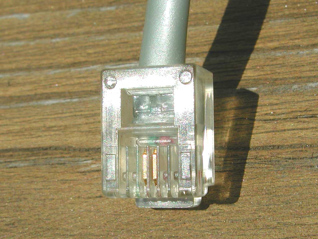
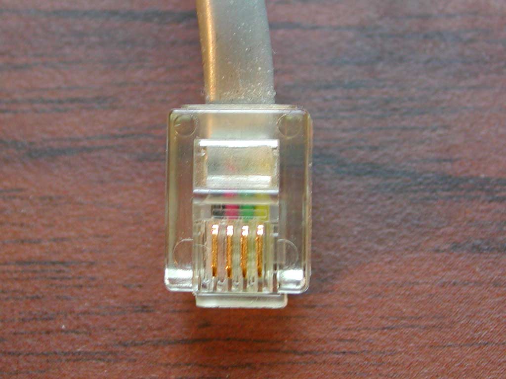
The first step is to notice what actually comes out of our telephone. If you look closely at the RJ-11 (registered jack 11), you'll typically see two gold (it is literally gold-plated, as gold does not oxidize &ndash “rust”) electrical contacts. And you may notice that there is a red and green wire connecting to these. These two wires are often simply called a pair, and are usually twisted to each other (though they are not twisted in the flat silver-satin cable used on most telephones, because this cable is so short it does not matter for these types of signals).
The green wire is called the tip, and is roughly at ground potential. The red wire is called the ring, and is at about -48 volts DC, as supplied by the telephone company.
3 of 61
This could be our mental image of a telephone network. We have a telephone, we know there's a cable coming out of the telephone (or the telephone base station if it is a cordless telephone) that somehow goes through our house and eventually to the phone company. We dial the phone, and somewhere the phone rings (or we get a busy signal, or a wrong number, or an answering machine).
Keeping it positive (and simple), let's say the other phone rings. Somehow, our telephone, and every other telephone in the world must be able to be connected together.
The first step is that all the telephones (normal, traditional, land-line telephones – cellular and other new telephones are another story) have a cable to the telephone network.
The telephone network is a complicated thing, so it is often drawn as a cloud, and called the public switched telephone network (PSTN):
- Public: The network can be used by anyone (that wants to pay).
- Switched: You can dial the phone (or more likely, press buttons) to connect to anyone (who has a phone).
- Telephone: Everybody has a telephone (or something that sends and receives the same signals as a telephone, such as an answering machine, a facsimile machine, or a computer modem).
- Network: Everything can send to everyone else.
4 of 61
Everyone's telephone is connected to a Central Office – often called the CO (or Local Exchange). This is a building owned by the telephone company (which is also called the Local Exchange Carrier – the LEC). The building is generally a mostly-windowless, well-kept, discreet building. Since the electrical signal from a telephone is very small (a few hundred millivolts), the length of the cable from the CO to our telephones is generally less than 5 km. An exception is in rural areas, where the customers (and therefore telephones) are so far apart that the phone company has to run much longer cables to serve enough telephones to make building a CO viable (and there is extra equipment required, and restrictions on the high-speed signals that can be carried).
Therefore, in urban and suburban areas, we all typically live within about 5 km of a CO.
A telephone line connects our telephones to the COs, and the COs are all interconnected with trunks (generally fibre optic cables running between COs).
5 of 61
Here is a map showing the location of the Central Offices for Toronto, which is about 40 km by 20 km. The Central Offices are generally 3 to 6 km apart, and there are about 30 in total.
6 of 61
Here's a telephone company Central Office. Well-trimmed lawn, one simple sign – a building you'd generally not notice. You'll also see a security camera at every corner, and lots of air conditioners.
Often, you can see diesel-engine backup power generators. Telephone networks must work even when there's a power failure, so they have racks and racks (all earthquake-proof) of lead-acid batteries. These batteries are the same chemistry as automobile batteries, but with a glass or clear polyvinyl chloride jar casing (so they can be easily inspected – they are expected to have a 20-year life), and providing -48 volts (direct current), and constantly trickle-charged by the power-line (and typically with capacity to provide eight hours of service in the event of a power failure). During a power failure, the back-up generators are to automatically start before the batteries run out. This is a great system, but during the August 2003 North America wide power failure, they discovered that the trucks which were to deliver more diesel fuel were running out of gasoline because the service stations had no electricity to run their gasoline pumps.
Usually, very few people work at a Central Office, as most activities (such as running tests to find noise on your line, and adding new phone services) can now be done remotely (including monitoring the security cameras).
In the photograph there is a fibre optic cable splicing truck parked at the CO overnight.
7 of 61
Here's another large central office. Again, not many windows, well-trimmed and neat. Let's have a closer look at that security camera.
8 of 61
The camera is mounted in the weather-proof enclosure (you can just barely see the lens through the protective glass), which is mounted on a motorized pan and tilt mount.
Above the camera is an infrared illuminator (this one is likely a standard halogen light bulb with an infrared filter &ndash newer cameras are more sensitive to low light levels and typically use infrared LEDs, which last longer and use less power). The infrared illuminator can be turned on so the camera can see at night (it is sensitive to infrared light) but people cannot tell that they are being illuminated (since people can't see infrared). A mesh in front of the illuminator ensures it can't be broken by people throwing stones.
9 of 61
Around back is a well-marked “co-location entrance”. Co-location refers to the telephone company (called the incumbent local exchange carrier &ndash ILEC) renting out space in their central office (they are forced to do this by government regulation) to competitors (called competitive local exchange carriers &ndash CLECs) who need access to the copper pairs to the phone company's customers' homes and businesses.
The phone companies offer access to their copper cable plant on a wholesale basis, so CLECs (there may be more than one in a given area) can offer DSL and other services without having to run their own copper pairs to every customer they may win. The CLEC's technicians are then allowed access to certain areas of the central office, to their own equipment located in the central office, which is typically mounted in locked cages, to ensure that everybody only has access to their own equipment.
10 of 61
Since a telephone company Central Office provides every telephone line which is connected to every customer (which they traditionally call a subscriber) within about a 5 km radius of the Central Office, there are thousands of copper pairs of wires leaving Central Offices.
The telephone company calls anything at a customer's location Customer Premises Equipment (CPE), and telephone company equipment that is outside of a Central Office (and is not CPE) is called Outside Plant.
Generally, a Central Office (the area served by a Central Office is sometimes called a Wire Centre) will handle all the phone numbers for an exchange, such as all the telephone numbers from 633-0000 through to 633-9999 (which is 10,000 phone numbers). The first three digits of a seven-digit phone number are often called the NXX, as “N” is any digit 2 through 9, and “X” is 0 through 9. In fact, Central Offices often handle many exchanges, so can have 50,000 or more pairs going to all the nearby houses, apartments and businesses.
Farther down this web page are pictures of everything, but first here's an overview ...
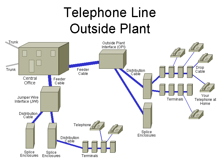
The pairs (each represents a single telephone line, generally one pair per house) leave the Central Office in Feeder Cables, which may have 900 to 3,600 pairs each. Feeder cables installed in the last 20 years or so will typically be buried (especially in urban areas), and older cables (and especially in rural areas) will typically be aerial (above-ground, on utility poles).
The feeder cables each go to a locked enclosure, typically called an Outside Plant Interface (OPI) or Jumper Wire Interface (JWI, pronounced “gee-wee”).
The OPI or JWI then splits the big feeder cables into smaller distribution cables (which may have 200 pairs each) that fan out to nearby streets. At a splice, these distribution cables then are split into smaller cables (perhaps 25 or 50 pairs each), which are then “looped-through” terminals along a street (that is, every pair is made available at every terminal in the string).
In the terminal, a drop cable is then connected to whichever pair is assigned to a customer, and the drop cable is then run to the customer's premises, to connect to the inside wiring, which is connected to all the telephones on that line.
11 of 61
This is a 1,200-pair cable typically used for outside plant. It is Polyolefin Insulated Conductor (PIC) cable, and is gel-filled with a gunky goo to keep any water from seeping into the cable, as this would cause cross-talk and other signal degradation. The colour code for the pairs and binder groups is described here.
This feeder cable will run from a Central Office to within a kilometer or two of the homes and other telephones whose lines it carries.
12 of 61
I'm sure you've seen enclosures such as this beside the road, sometimes with a technican too. This particular enclosure is called an Outside Plant Interface (OPI) and is made by 3M corporation.
This enclosure receives up to 900 pairs (each is a separate telephone line, with its own telephone number) from its Central Office, and allows each pair to be connected to any one of up to 1,800 pairs which then provide all the telephone services to the nearby houses.
Typically, if a pair is defective, the problem will be in the pairs between the OPI and the homes (these go through more locations where they can be damaged), which is one reason why there are extra pairs towards the houses.
The technican here has a butt set. Some people say this name is because the technicians wear these on their butts. Others say they are called butt sets since they enable technicians to butt-in to your conversation (by connecting to your telephone line at this enclosure). Since there are now usually extra pairs brought from the Central Office to this enclosure just for such conversations (or the technicians simply use a cellular telephone), it is rare now to hear a technican using your telephone line.
Typical technician activities at OPIs include connecting a telephone line from the Central Office to a different pair (to avoid a noisy line), and connecting a telephone line from the Central Office to an unused pair for a customer who has ordered an additional telephone line.
13 of 61
Here you can see that the top of the OPI is unused as it has had a still-unused expansion installed recently (making the enclosure taller). The white horizontal modules are punch-down blocks (so called, since the electrical connections are made by using a punch-down tool, and hitting it with the palm of your hand, to wedge each wire into a V-shaped electrical contact). 3M's punch-down system is called MS2 (Modular System Splicing), but there are many other similar telephone wiring systems.
This enclosure is compact, as it has punch-down modules on both sides (though technicians don't like this, as this requires them to frequently walk around to the other side).
14 of 61
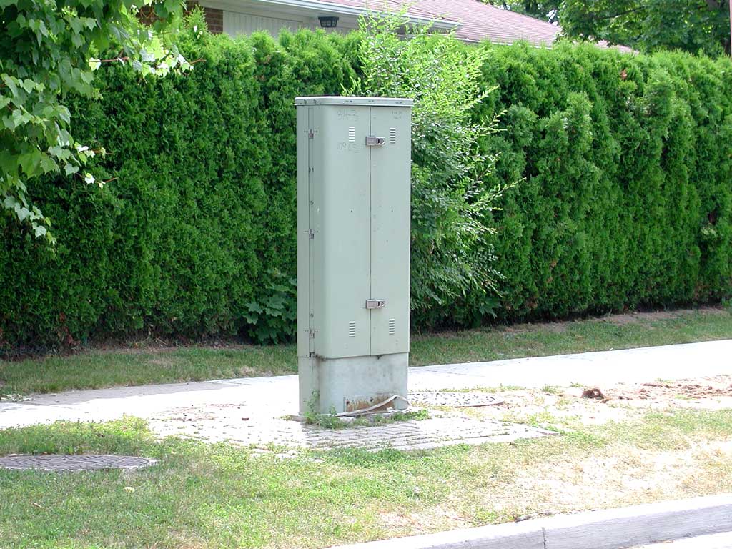
This is a newer enclosure, called a Jumper Wire Interface (JWI), made by Nortel (or it was, before they got rid of most of their copper-related businesses and sold it to Siecor which is now called Corning Cable Systems, and they now call it MOXS, the Modular or Multi-purpose Outdoor Cross-Connect System, read all about it here). This cabinet does the same thing as an OPI (that is, it connects the telephone line pairs from the huge feeder cables from the Central Office to smaller cables for distribution). However, for this type of enclosure, all access is from one side.
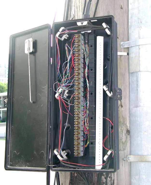
15 of 61
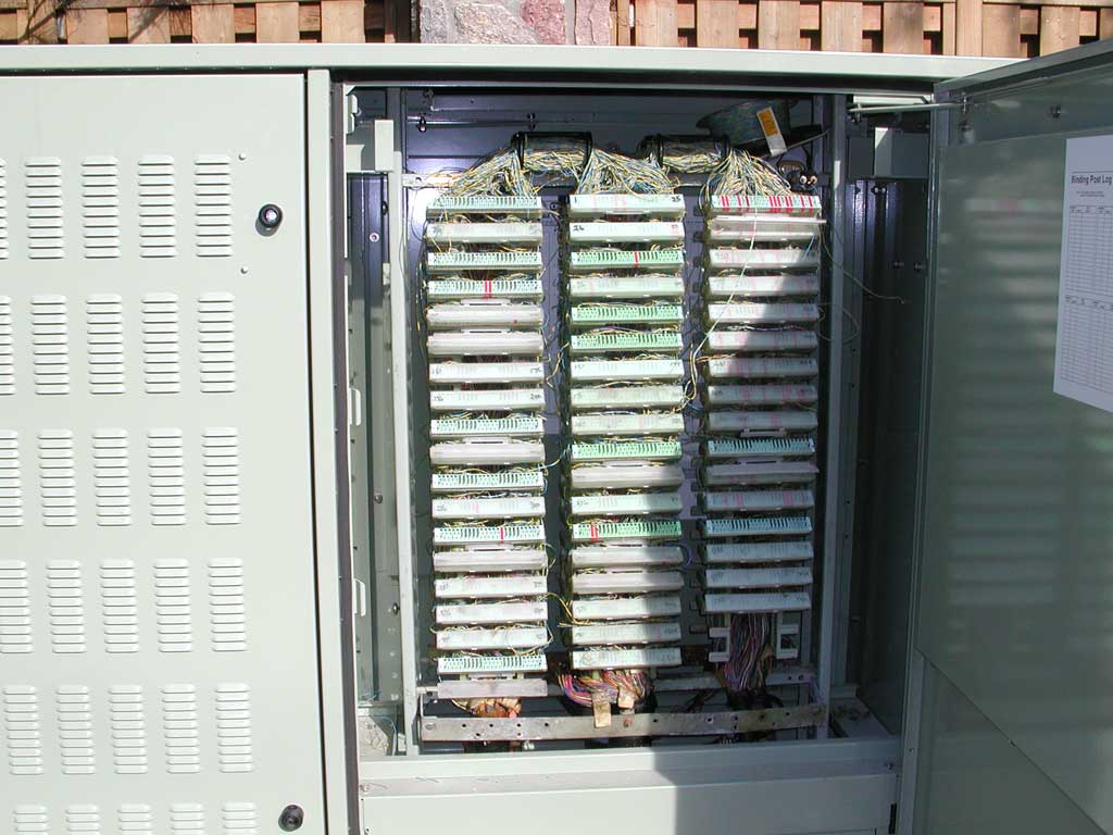
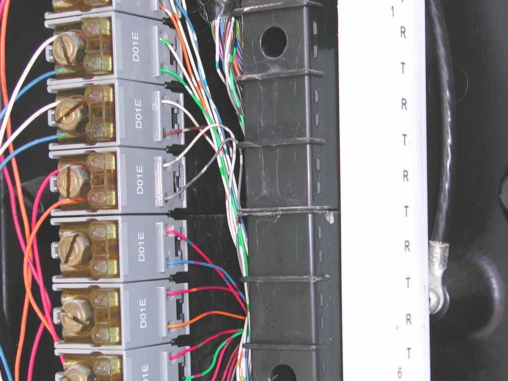
Here is a view with the doors open.
There's a spool of blue/yellow jumper wire at the top-left.
The punch-downs with the green retainer covers are the pairs from the Central Office, and the punch-downs with the blue retainer covers are the pairs to the customers.
There are 25 pairs per punch-down wafer, so the full column of punch-downs (second from the left) has 200 pairs from the CO, and 400 pairs to the customers. If it was full, this JWI therefore has room for 1,000 pairs from the CO, and 2,000 pairs to customers.
Note the (unused) “clip board clip” for a technician to hold his work order.
Near the top on the left side-panel, and again near the bottom on the right side-panel are two (in this case unused) brass posts to terminate the order wire used to communicate with technicians in the CO. This is a standard telephone line, so the technicians don't need to use some random person's telephone line. Often, the same phone line will be used for several JWIs. Sometimes technicians will leave a pair of wires attached to these posts so they can more easily attach the clips of their butt set. If these wires have exposed copper (they call this a shiner) which touch the door when it is closed, then the phone line won't work in all the JWIs, so they still need to use someone's phone line when they need to contact the central office.
16 of 61
This is a smaller JWI that has room for two columns of punch-downs, for a total of 1,200 pairs. These are often used in rural areas.
17 of 61
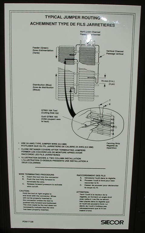
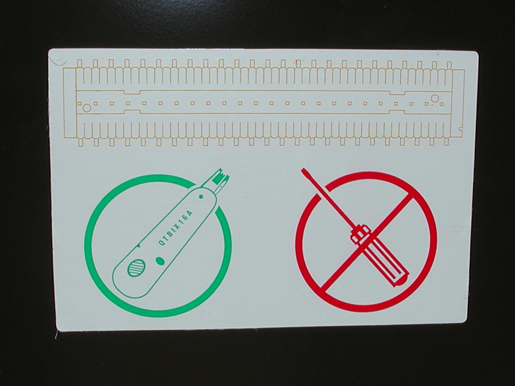
Here's a reminder for technicians:
- To only use 24-guage pairs.
- To route all jumpers around the punch-downs, and to leave three inches of slack.
- The correct punch-down procedure to be sure the wires are fully seated into the connector
18 of 61
A reminder to technicians not to try to use a screwdriver to jam the wires into the punch-down wafers, and of what the correct punch-down tool is.
19 of 61
Note how much smaller the “foot-print” (amount of real-estate) is for this OPI. Some vendor information is here.
20 of 61
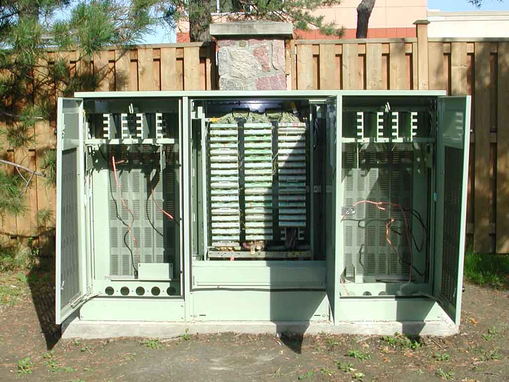
The main thing that happens in this OPI is to connect the feeder pairs from the Central Office (which are punched-down to the centre column of modules) to the distribution pairs (which are on either side of those modules). The mass of jumper wire pairs above the modules is all of the jumper wires between these two sets of modules (each carrying someone's telephone line signal).
There are 25 pairs per module, and 18 modules per column, for a total of 450 pairs per column, and 1,350 pairs on this side of the OPI.
This product line is described here.
21 of 61
This is a close-up of the 900-pair cable coming up from underground to the centre modules. The white cover protectors over the punch-down modules have the pair numbers written on them. Pairs 1 through 450 are in the left column of modules.
22 of 61
Here's a close-up of the wires terminated onto a MS2 Quick-Connect Module. This is an outdoor style with the gunky grease, so some of the wires are covered. You can see the top edge of the electrical contact's V-shaped blade into which the wire is inserted by the impact tool.
For some reason, the wire on the left does not seem to be properly connected, and there are unused wires (of the wrong colour) at the bottom of fifth, sixth, and eighth contacts.
23 of 61
This little red plastic piece is a 4014 Priority Circuit Cap to “to protect circuits from accidental interruption”. These are generally used for data circuits to ensure that technicians don't use these pairs to try to find dial-tone when they need to make a phone call.
24 of 61
This is a very close view of a similar punch-down. This one is called a BIX (building industry cross-connect) wafer, made by Nortel, though this business is now owned by Belden CDT Networking (NORDX). Between the fingers you can see the inside edges of the “V” of metal. When the wire is jammed in by the technician's punch-down tool, the insulation is moved away (hence it is called an insulation displacement connector – IDC), allowing a gas-tight (so no air can get between the metal-to-metal contact to oxidize it) connection.
25 of 61
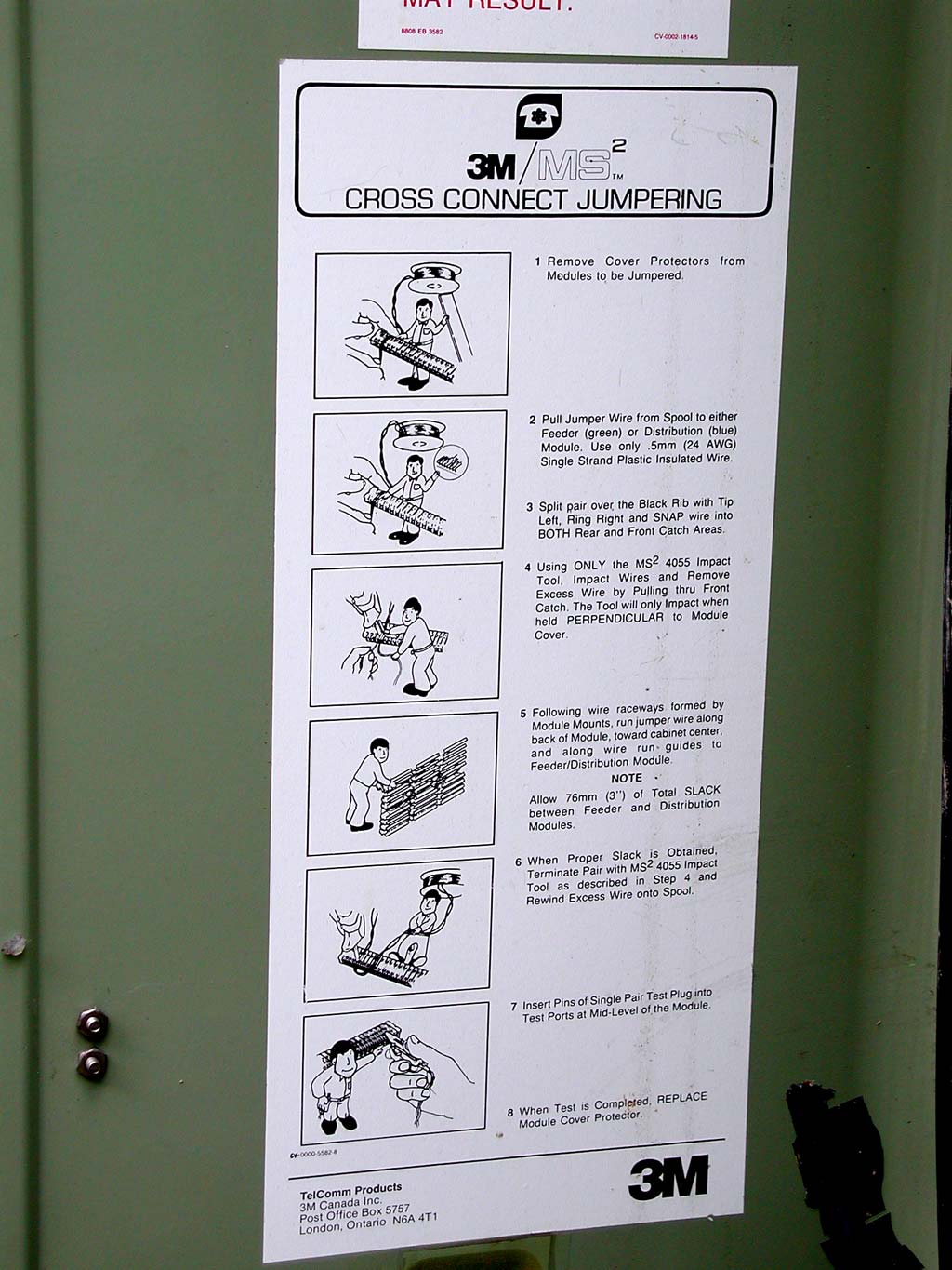
Here is an informational poster on the inside door of the OPI. It reminds technicians:
- To use only 24 gauge (the metric equivalent is 0.511 mm diameter) copper wire with plastic insulation (very old telephone cable used paper insulated cable, which isn't compatible with the IDC connectors).
- That the feeder pairs from the central office are on the green modules, and the distribution pairs are on the blue modules.
- That the tip wire of a pair goes on the left side, and the ring conductor is on the right side.
- To leave some slack in the jumpers which they install (these connect the pairs from the feeder modules to the distribution modules).
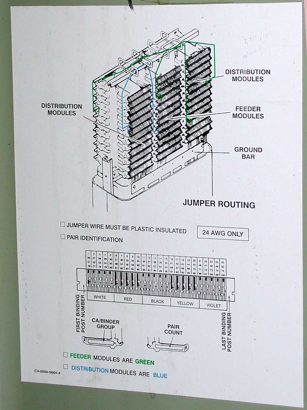
26 of 61
This poster notes that this door is considered the front of the OPI, and that the distribution pairs (which go towards the customers) 1 through 450 are on the left column of blue modules. So: pairs 451 through 900 are behind that column (accessible from the back of the OPI), pairs 901 through 1,350 are on the right blue modules, and therefore that pairs 1,351 through 1,800 are accessible from the back of the OPI. Feeder pairs (from the Central Office) 1 through 450 are in centre green modules, so feeder pairs 451 through 900 are behind that.
27 of 61
This poster reminds technicians to route all jumper pairs through the guides above the modules.
Below that, it shows that the top of each module has short or long black lines to help technicians count up. There is a standard colour code used for 25-pair cables, where each group of five pairs has a wire that is: blue, orange, green, brown, or slate (grey). The first group of five such pairs is twisted with a white wire. The second group of five pairs is twisted with a red pair, and so on, through black, yellow, and violet (hence the helpful colour names printed below the module).
The full 25-pair colour code is here (courtesy of General Cable, a major manufacturer of such cables).
28 of 61
This shows the jumper wire routing for the not-yet-installed expansion modules (at the top), which have capacity for 12 more feeder modules (which is 300 pairs) and 24 more distribution modules (which is 600 pairs).
29 of 61
Here's a nice new OPI, used as an expansion to an existing OPI.
30 of 61
Here's a look inside. The two side sections are empty, except for heavy-gauge copper ground wires.
31 of 61
This is the left side. It is likely that active (that is, powered, and heat-producing) equipment (such as a DSL concentrator) is to be mounted here in the future, as the three ouside cabinet sides have lots of screened (to keep the bugs out) ventilation slots.
Each section of the cabinet comes with a yellow (3M calls it gold) MS2 4055 Impact Insertion Tool, and a 4047W Pair Test Plug Assembly.
32 of 61
Here is the impact tool. The metal end is spring-loaded and when pushed in, the spring releases a weight like a little hammer hitting the end. This properly seats the copper conductor to make a gas-tight connection, and cuts-off the excess wire (below the connection). Some instructions are here.
33 of 61
This is the pair test clip. The retaining clip and one of the prongs are spring-loaded, so it can be clipped onto a module to provide electrical connection for test equipment. Some information on it is here.
34 of 61
But here's my favourite part. This entire new OPI cabinet has been placed directly over the module rack of the previous little cabinet. Therefore, the existing connections are not disrupted or changed. At the bottom you can see the corroded ground bar and old feeder and distribution cables.
35 of 61
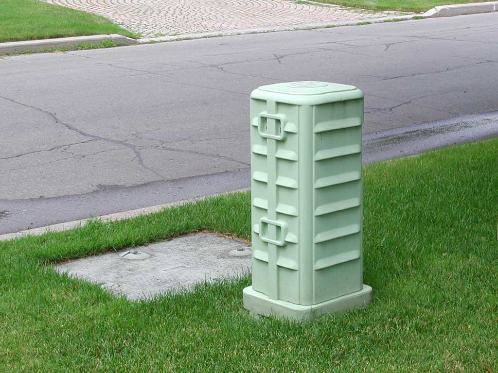
The distribution cables leaving the OPI towards people's houses are in cables smaller than feeder cables, for example, 200 pairs. These 200-pair distribution cables run closer to people's houses to a splice, where smaller cables (such as 50 pairs each) will fan-out along each street. This pedestal can have a splice in it.
36 of 61
You may wonder what this colourful mess is.
37 of 61
It is a splice in the midst of being reorganized (I hope!).
These are 3M Modular System Splicing (MS2) modules. As pictured here, these “4000 series” modules are for connecting a group of 25 copper pairs to another 25 pairs (so the end of one cable connects to the beginning of another). Another common use is for “bridging” (making a “T” connection) so one 25-pair cable can connect in the middle of another.
Some information on the 3M MS2 system and cable splicing is here, and some details on the modules themselves is here.
38 of 61
Here is a close-up of pair 25 (the violet/slate pair) pressed into the body of the module, connected to pair 25 of another other cable below it. You can see the nasty environment of outside plant, where a reliable electrical connection must be maintained even though the connector may be wet and dirty.
When individual wires (rather than 25 pairs) need to be connected, a 3M Scotchlok splice is usually used. This allows two or three wires to be electrically connected, and you can see a few (the red round things) in the mess picture, a few before this one. Some information on 3M's Scotchlok system is here.
39 of 61
These yellow covers are 3M 4075-S Sealant Boxes and they have a gel in them, so when the terminal strips are pressed into them, the connections become water-proof.
40 of 61
Here is a really old splice. It receives a buried 200-pair cable from the OPI, and has four buried 50-pair cables going out, along the adjacent residential side streets.
Since these splices have the same number of pairs entering and leaving, there isn't any reason to switch around the pairs, so it is rare to see technicians working at these.
One trouble-shooting activity at these is to determine why pairs don't work. Here a technican will typically sit on a little stool, and start with a list of known bad pairs. They will then separate the splice and connect a time domain reflectometer (TDR) to the pair towards the terminals and houses. A TDR (in this case) is a hand-held device, and is sometimes called cable radar, as it sends a pulse down the pair, which will be echoed back, according to the cable problem (such as shorted, or open circuit). By measuring the time delay until the echo is received, the TDR can indicate the distance down the cable to the problem. Working with the telephone company's as-built drawings and maps (which the technician typically accesses from a wirelessly-connected laptop computer), the location of the problem (such as at the terminal, in the third house's backyard) can be identified and by walking over there, hopefully, the technican can fix the “finger” problem (usually caused by other technicians), perhaps the cable being pinched by the door of the terminal.
41 of 61

The 50-pair cable from the splice “loops-through” these, so the same 50 pairs are available at every terminal along the cable – and, unfortunately, also allowing each pair to be shorted or damaged at each terminal (which is more likely as the wire can get caught when the cover closes, and the conductive aluminum will short or ground the wire, so that telephone line will be noisy or will not work at all).
42 of 61
Here is a pedestal missing its cover.
43 of 61
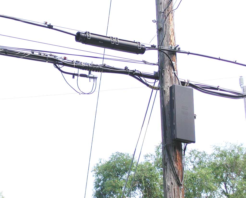
The black, flat, plastic enclosure is a more recent (and reliable) type of terminal, (some documentation on this model is here). A (perhaps) 50-pair aerial cable (the upper one) is lashed (with a spiral-wrapped wire) to a steel messenger cable (often called a strandwhich provides support.
A splice closure (the black, plastic tube, which is “re-enterable” – note the latches) covers the connections to a 25- or 50-pair cable stub (which is attached at the factory to the terminal, and the cable stub is spliced to all the pairs of one or two 25-pair binder groups in the aerial cable when it is installed). The cable stub enters the terminal from the top (through a water-proof boot).
In areas with large single-family houses, 25-pair terminals are installed every few poles, with the service line running along the 50-pair cable back towards the house until it can be run directly to the house without hitting trees). When houses are closer together, or there are multi-family dwellings, terminals may be installed in every utility pole, and 50-pair terminals may be used.
Drop cables (typically with one to four pairs each) are then run from the terminal to the nearest houses, you can see three or four drop cables exiting from the bottom (so the holes don't let rain in), and running back up the pole, and they split in different directions running to the left, just below the splice enclosure.
The drop cable is sometimes called “figure-8” cable, since that is what the cross-section looks like (some information is here). The top is an insulated steel wire, to provide strength. The bottom is the jacketed copper conductors.
44 of 61
Here's the inside of a terminal enclosure. The metal arm hanging down on the inside of the door can be used to ensure the door doesn't swing closed while the technician is working in it.
A factory-installed 25-pair cable, with a water-proof boot, enters at the top centre, and runs down behind the white plastic cover running down the centre. The cover is pre-labelled with the pair numbers, and the Tip and Ring designation.
A column of 25 pairs of lightning protector blocks runs down the left side of the enclosure, and another 25 pairs of lightning protector blocks can be installed down the right side of the enclosure. These blocks are grounded, and if the cable is struck by lightning, the protector blocks divert the current through the ground wire to limit the voltage on the pairs, hopefully protecting the customer's telephone equipment, and that at the telephone company's central office.
The drop cables to people's telephones run through rubber-gasketed openings in the bottom. Cable guides allow the technician to route the drop cables neatly.
45 of 61
Here the white cable cover has been removed, and you can see the 25 pairs running down the centre.
46 of 61
Here's a close-up of the lightning protection blocks, showing the wire pairs from the central office running in on the right side, and the individual pairs to people's homes coming out the left side. The lightning protection blocks often fail when the cable is struck by lightning, so the gas tube arrestor can easily be replaced by unscrewing the brass screw.
47 of 61
Here is a close-up view of a single lightning protector.
48 of 61
Here the lightning arrestor has gone to pieces. The important part is the little cylindrical thing (no doubt manufactured in April 1987). This is a gas discharge tube, and inside this hermetically sealed capsule are two contacts separated by a precise distance so that above a specified sparkover voltage, the gas in the tube will conduct, hopefully clamping the voltage low enough that connected electrical and electronic devices will not be damaged.. At the Thunder Electronic Engineering Company (of Tehran, Iran) website, it notes that their CITEL division (which they acquired in 1976) acquired the Claude gas tube line from GTE Sylvania in 1992.
49 of 61
Here is a different style of terminal where it is a cylinder around the cable. This happens to be the end of the line, so the cable is terminated after exiting the terminal. With other styles of terminals, the cable at the end of the line ends inside the terminal.
50 of 61
Perhaps your aerial telephone cables have this black plastic covering, with a tented cross-section (and some hanging down). This is squirrel guard, and is used to prevent squirrels from chewing through the cable jacket and damaging the telephone cable. As described here, current telephone cables are available with a steel tape armor, so the squirrel guard is no longer needed.
51 of 61
New installations typically use two-pair aerial drop cables, as shown here on the right (at the left is a cable TV coaxial cable), with wedge-style cable clamp, anchored to the side of a house. The drop cable then goes down the side of the house. Buried service lines often have three pairs.
52 of 61
Here is a very close view of the cross-section of the drop cable, which is type ADP NMS from Superior Essex Inc. Their catalogue page for this cable is here.
At each of the four corners is a strong thread to provide strength, as this cable is designed to be self-supporting, and does not need a carrier strand to support it. As shown here, the cable can be strung up to 400'.
The two solid copper pairs can be clearly seen.
Interestingly, even though this cable is being installed for new installations (many of which will be used for high-speed data using DSL), the data sheet only provides characteristics up to T1 (1.544 Mbit/s speeds). Another interesting technical point is that the characteristics are measurably different when the cable is wet, and the cable elongates when heavily loaded (for example, due to ice), which would also change the characteristics.
53 of 61
Here we can see the two 22-gauge copper pairs. As described in the above data sheet, the white wire is the tip, and the solid colour wire is the ring conductor. The long white thread is the ripcord to facilitate removing the cable jacket. The shorter white threads are the strength members.
54 of 61
This is the cable clamp. It is an ingenious design that uses the tension to tighten a wedge to grip the drop cord.
55 of 61
Here the clamp is disassembled. The ridges along the bottom piece, and the bumps embossed into the metal plate grip the drop cable.
56 of 61
The drop cable then goes down past this demarcation point (or demarc), and enters it from the bottom (so rain doesn't get in). This is called a demarc, since it is the dividing line between cable which is the telephone company's responsibility, and the in-house wiring that is the reponsibility of the customer. The white cable exiting the bottom goes into the basement, and has the two pairs needed to support a two-line telephone service. The black wire exiting the bottom is a ground wire, which is clamped to either a copper water line, or a metal stake driven into the ground (to be sure it is at ground potential).
Note this enclosure has provision for the customer to put their own padlock on it, since opening this enclosure would allow others to get access to the customer's phone line. By connecting any telephone to the phone line, others could then make long-distance calls, which would come from the customer's phone line, and therefore be charged to the customer.
57 of 61
Here the demarc is opened to show a part which the customer can access, and a separate enclosure in the centre, which is for the phone company to access.
58 of 61
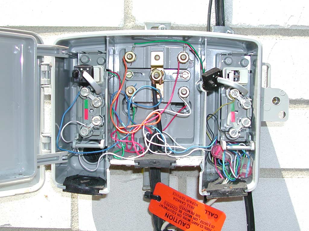
- At the top-right and top-left are standard RJ-11 telephone receptacles (jacks). The RJ-11 plugs (the top-left one is plugged-in, the top-right one is unplugged) have a black rubber boot to make them slightly water-proof, and connect the in-house wiring to the telephone line. Standard RJ-11 connectors are used so you can plug a standard telephone directly to the telephone line, to bypass your in-house wiring to help determine whether a problem (such as a noisy or dead line) is a phone company problem, or due to your in-house wiring.
- The large brass nut in the centre block is a ground lug, and the heavy wire provides the ground connection. The block has lightning protectors (also called carbons) to provide some protection against lightning strikes to the telephone cable from damaging your telephones. Often, due to lightning strikes, these fail (resulting in a very noisy telephone line), and need to be replaced.
- Basically, this device has two telephone lines (each a pair of conductors) coming in from the aerial drop cable, and going down into the basement of the house.
59 of 61
The pairs then go through your walls and ceilings, until you get to the RJ-11 connector for your telephone.
If you look close, you'll see that there is actually room for six wires (which is three pairs of wires, which is three telephone lines) on this connector.
60 of 61
If you have two telephone lines on a single connector, then it is called an RJ-12, and would look like this.
You can see that the insulation for the second line is yellow and black, and the contacts are to the outside of those for the first line.
61 of 61
So, we've discussed the outside cable plant, from the Central Office, through to your telephone.
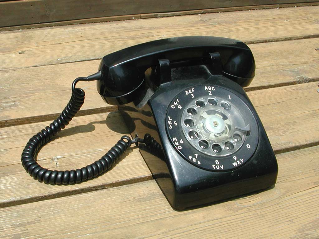
As a side point, this traditional dial telephone is called a “500 set”. The updated version of this (which has a keypad) is called a 2500 set.