Initially cable TV was used to distribute the signal from a tall, shared antenna for all the televisions in a community, so this was called CATV – community antenna television (sometimes called MATV – master antenna television). The term multiple system operator (MSO) refers to a cable TV system operator (or cable TV company) as they would frequently operate many cable TV systems.
Now the cable TV network has become a distribution method for many signals, including; cable-only programming and specialty channels that are not broadcast over the air, as well as pay-per-view television (PPV) and video-on-demand (VOD). Recent enhancements to the CATV infrastructure support two-way communication channel to support requesting pay-per-view and video-on-demand through the television set-top box interface (rather than subscribers needing to use a telephone-based system) and to provide high-speed Internet access and voice telephone service.
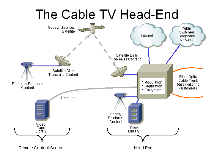
The head-end is the location where all the signals are received and gathered for distribution to the subscribers, this includes:
In March of 1941, the US-based National Television System Committee (NTSC) issued the technical standard which is still the basis for all North American television. Among the specifications was that each channel occupies a 6 MHz range of frequencies, with channel 2 at 54 MHz to 60 MHz, channel 3 at 60 to 66 MHz, and so on. The more channels a cable TV company wants to offer, the wider the range of frequencies that their cable plant (coaxial cable, amplifiers, taps, and so on) needs to carry.
In addition to wanting to be able to carry more channels, cable television companies also want better control over which channels each subscriber can view (so they can offer flexible packages of channels). These and other needs resulted in a migration to digital television, where a group of channels are digitized and compressed to fit into a smaller range of frequencies than the initial, analogue, system could carry. The digitized signal is also encrypted, so you can only see the channels which the cable company authorizes your set-top box to decrypt. Cable television companies really like digital service since they can leverage their investment in outside plant infrastructure to get even more channels carried, and therefore more revenue.
Each subscriber then needs a set-top box to decrypt and decode the digitized and compressed signals back to standard analogue, to be received by standard televisions. Since each subscriber requires a set-top box (which is an intelligent, microprocessor-controlled device), with two-way communication to the head-end, the cable company can control which channels every subscriber can watch. The cable company then portrays digital television as being higher quality, to convince you to pay extra for it, even though most of the advantages are to the cable company, not the subscriber.
Racks and racks of equipment (in secure, raised-floor, air-conditioned computer-type rooms) then shift these signals (the traditional analogue channels get the low channels, and the new services, such as digital television and cable and telephony modems get the higher channels) to different channels, so you can select each individually according to the channel you flip to on your television (the cable TV company remotely controls your cable and telephony modem to share channels and bandwidth among many users).
While traditional cable TV networks used only coaxial (so called since the two conductors share an axis) cable, to provide higher-quality and more reliable signals, current cable TV networks in larger cities use a combination of fibre optic cable (to get the signals close to your home), and then coaxial cable for the last few kilometers to your house.
2 of 46
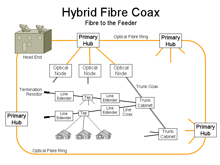
Many networks now bring the fibre closer to their customers, so that fewer customers are sharing a fibre optic cable. This allows new services, such as video-on-demand (VOD, where each customer can watch any movie at any time, and pause and rewind it) so some customers (those currently watching VOD) are the only ones (fed by that fibre) watching a particular channel at a particular time. Such systems are called Fibre to the Feeder (FTTF). The term feeder refers to a cable which serves a device which then connects to the distribution cable that connects to the end users.
The ring might consist of 96 strands of optical fibres running from the head-end to a first primary hub, and then another 96 strands running from that primary hub to the next, and so on, until the signals arrive back at the head-end. Primary hubs may serve 4,000 to 250,000 customers – perhaps an average of 100,000 customers each.
Any time cables are run through public spaces (buried underground, or aerially along utility poles), they will occasionally be damaged by construction back-hoes or automobile accidents. The advantage of the ring is that it can be configured to be self-healing, so that if there is a cable break, the signals are automatically (within 50 ms) routed around the break, so service is not interrupted.
The primary hubs will be a few 19" racks of equipment, in secure buildings, with battery backed-up power supplies, air conditioning, and remote monitoring.
3 of 46
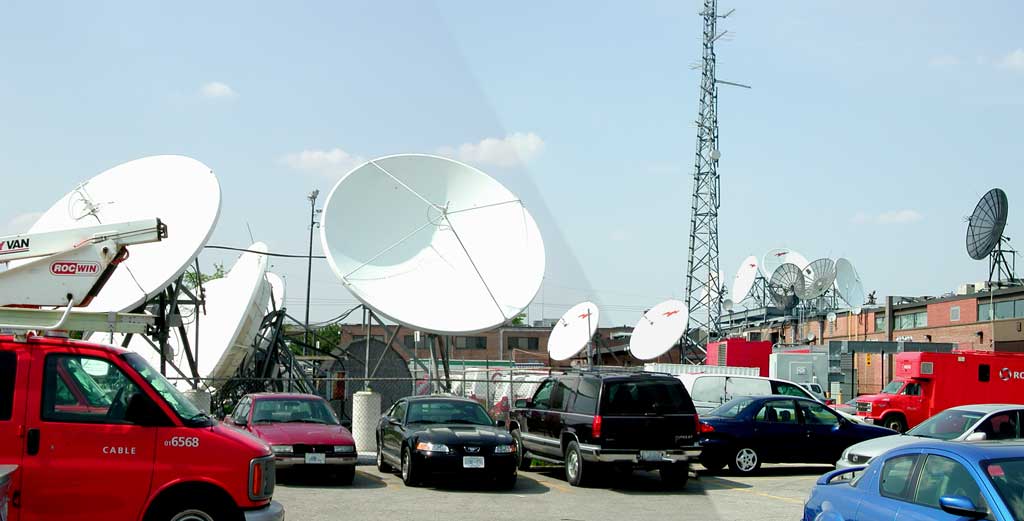
As you may know, the earth isn't flat (actually, it isn't a sphere either, it is an oblate spheroid – a flattened ball – due to the centrifugal force of the earth's rotation being greater at the equator).
Also, higher frequencies (such as those available for use by terrestrial and satellite microwave communication systems – that is, greater than about 1 GHz) are quite directional (sort of like a focussed flashlight beam) and require “line of sight” between the transmitting and receiving antennas. There must not be any buildings, trees, or curvature of the earth between the antennas. For greater distances, this requires the antennas to be higher above the ground, and for even greater distances (for example, more than 30 km), the antenna towers either become so expensive, or sway in the wind so much that they don't stay aiming at the receiving antenna, with the result that direct communication between two antennas using microwave frequencies over distances greater than about 30 km doesn't work.
This limitation was known many years ago, and a solution was proposed by the famous science fiction writer Arthur C. Clarke in 1945. The idea was to use space-based satellites to relay information from earth, back to earth. The satellites would be high enough above the horizon that the curvature of the earth would not be a problem.
You may also know that the earth rotates, and if a highly-directional satellite antenna is going to be exactly aiming at a satellite, then the satellite must rotate around the earth at exactly the same rate as the earth rotates. The result is that the satellite is always exactly where the antenna is aiming, even though the earth turns.
The force of the earth's gravity decreases on objects (such as communication satellites) which are farther from the earth. Also, as a satellite rotates around the earth, centrifugal force pulls it away from the earth. To have the satellite “float” in space the centrifugal force pulling the satellite away from the earth must exactly match the gravitational force pulling the satellite towards the earth. This occurs at a height of exactly 35,800 km (22,225 miles) anywhere directly above the equator. In honour of the thorough examination and explanation of this by Arthur C. Clarke, this is called the Clarke Belt (or Clarke Orbit).
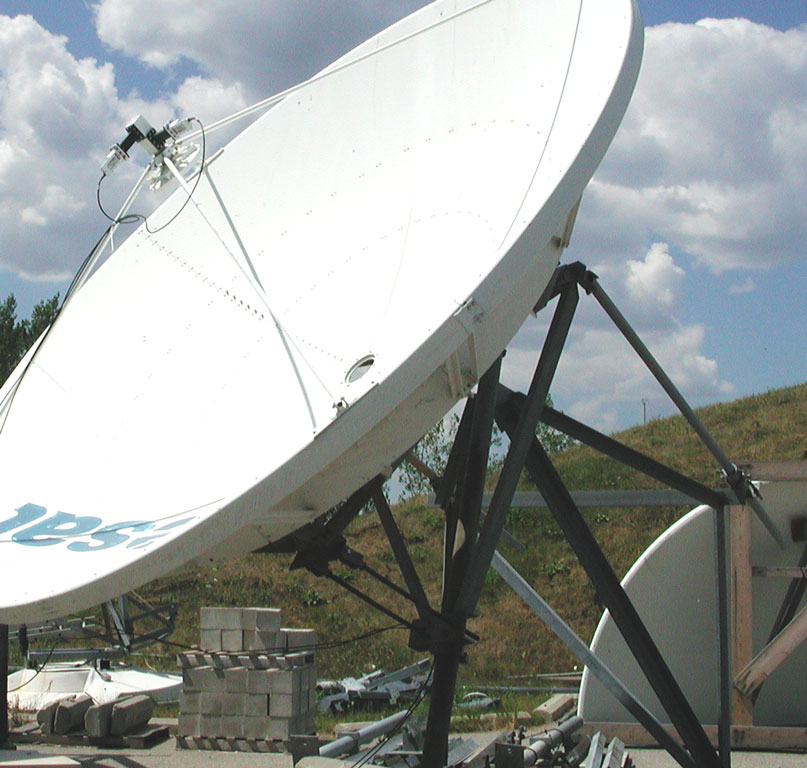
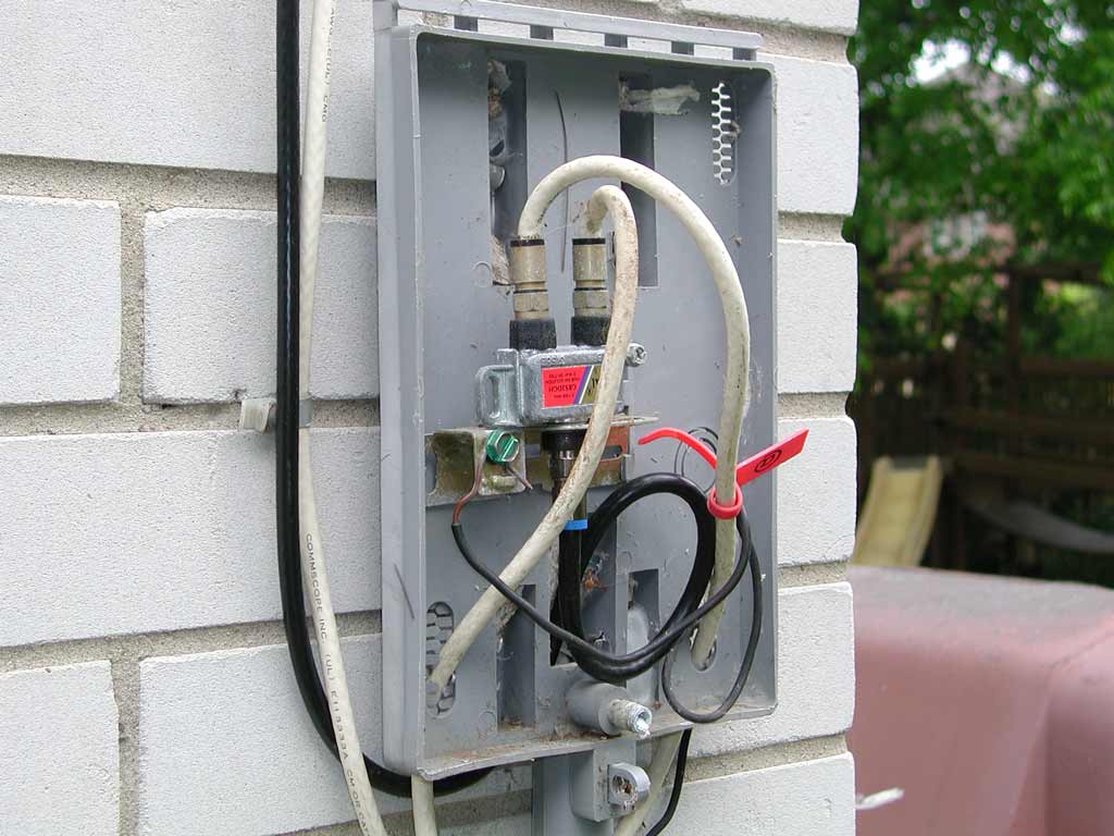
At this huge distance above the earth, the signal received from a satellite is very weak. To gather enough signal to be “heard” above the background noise, the satellite dish antenna has to be very large. The shape of the dish is a circular paraboloid, as this is the only shape which will focus satellite signals from the entire dish to a single point, which is called the focal point (which is analgous to the centre of a circle). The signal receiver is located at the focal point (in the above picture, you can see the coaxial cables running to the receiver located at the focal point &ndash in fact there are two receivers, 90° to each other, which is sometimes done to allow two satellites to occupy the same orbital slot, one with horizontal polarization, and the other having vertical polarization).
7 of 46
Each optical node will drive up to six coaxial cable trunks (or feeders).
Each trunk will drive up to six distribution lines, which in total will serve an average of 300 to 640 homes (depending on the assumptions made by, and the experience of, the cable company for the number of homes in that area which will subscribe to advanced services such as high-speed Internet, cable telephony, and VOD). A data sheet for a typical optical node is here.
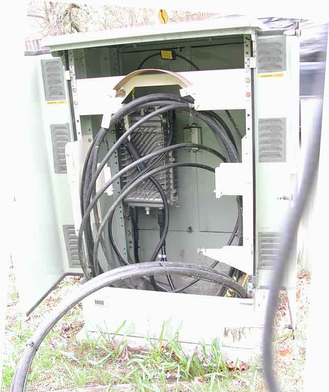
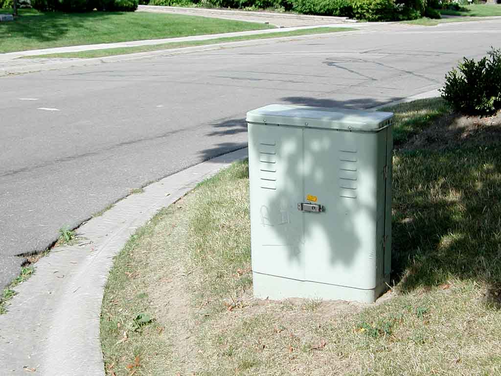
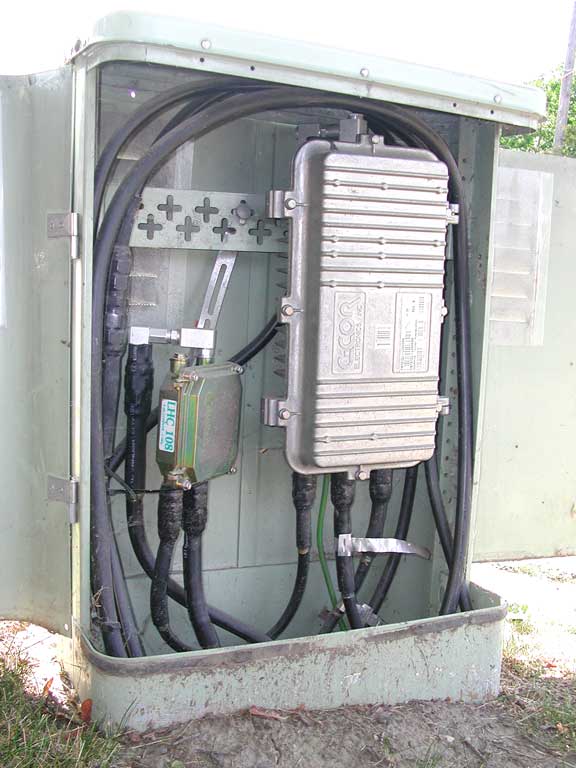
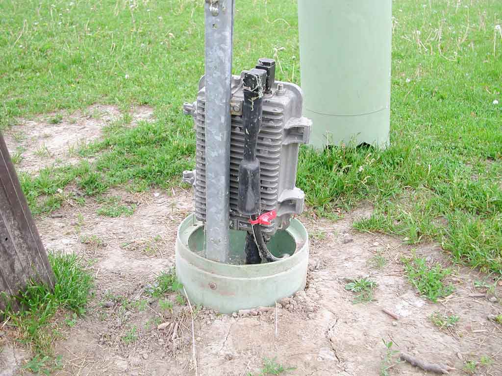
In this green cabinet (cable companies, and therefore their suppliers, are trying to make these ugly cabinets as inconspicuous as possible), at the back, the cast aluminum enclosure (with the nice heatsink pattern which allows good convection airflow for both horizontal and vertical mounting) is an optical node. You can see the fibre optic cable entering the optical node at the top-left (the fibre optic cable has the yellow warning tag at the top). This optical node is driving four trunks (the two thick, black coaxial cables attached to the bottom of the optical node, and two more at the top – these top ones both have 180° adapters, so the coaxial cables also go down).
10 of 46
This green pedestal is made by Channell Commercial Corporation, and some information on it is here.
13 of 46
This is a trunk cabinet, and inside is one trunk amplifier. It receives a trunk input (either from an optical node, or from another trunk cabinet), and provides distribution line outputs (and likely has a trunk output to drive the trunk amplifier in the next trunk cabinet).
14 of 46
On the left is a passive (which means it does not require power to operate) directional coupler. In this case, it is a model LHC 108, made by Lindsay Electronics. Their data sheet here shows this is an 8 dB directional coupler with three ports. One port is for the connection from the upstream device (towards the head-end), the second port is for the trunk cable to continue to the next trunk cabinet, and the third port is for the trunk amplifier, seen here to the right.
A coupler is generally a bi-directional device, as is required in this network since it is necessary to both send the television and other signals to the customers, and receive Internet traffic (and set-top box responses) from customers back to the head-end. The “8 db” means that the coupler's third port has a tap loss value of 8 dB (this greater attenuation is no problem since this output goes into the adjacent trunk amplifier which has been configured for this signal level), therefore allowing the coupler's second port to have less loss (so there is more signal power left to continue down to the next trunk cabinet). The thicker coaxial cable coming out of the bottom of the directional coupler (that's port two on the right) is the trunk cable, which continues to the next trunk cabinet (thicker cables have lower loss than thinner cables). The thinner cable coming out of the directional coupler's third port loops up into the bottom-left of the trunk amplifer.
Instead of a directional coupler, a traditional one-way-only cable TV network (that is, it sends the cable TV signal to customers, and does not support receiving anything from customers) would use a splitter (rather than a coupler), such as the Lindsay Electronics LHS 102, which is a two-way splitter. Splitters divide the input signal equally between the two outputs (and also pass the 60 volt AC power to each output, as do couplers). Splitters are used where the distribution line must be split to also run along another street. A three-way splitter would be used where there are two side-streets, and the distribution line also has to continue down the main street.
Anyways, back to this picture. This trunk amplifer receives the trunk input from the couplier, and provides three distribution line outputs (the two coaxial cables on the bottom-right, and the one at the top). This trunk amplifer is made by C-COR Electronics, Inc. The white sticker on it says FlexNet Trunk (900 Series), FNT91DJ–LO6H6R4 and the data sheet is for this series here shows this model therefore has the following:
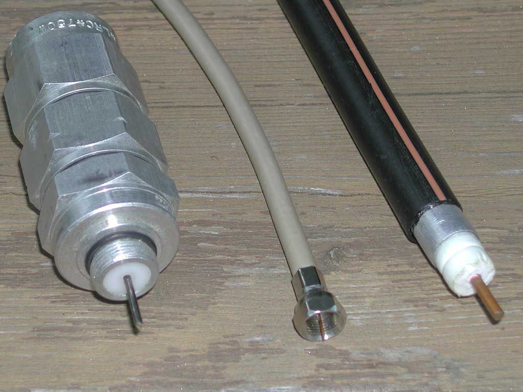
In the middle is the classic “cable TV coax”. It has a characteristic impedance of 75 Ω (the ratio of the voltage to the current at a given range of high frequencies), and uses an “F-type connector”. It has a braided shield (of very fine wires, making the cable quite flexible) under the jacket. The centre conductor of the cable is also the centre conductor of the connector. It is made of copper (for lower electrical resistance) covered steel (for strength). Therefore, you will damage your fine wire strippers if you use them to cut this cable.
At the right is the type of coaxial cable used for cable TV distribution lines, this (and the even thicker and stiffer trunk coaxial cable) is called hardline (since it is not flexible). It has a large diameter (providing lower signal attenuation) and thick aluminum shield (providing excellent noise immunity) and thick center conductor (providing both the required characteristic impedance and the high current-carrying capacity for carrying the 60 Hz power for the trunk amplifiers and line extenders). These cables are almost as stiff as the copper pipes in your home.
At the left is the type of hardline connector used for cable TV trunks and lines. It is clamped onto the end of the cable.
16 of 46
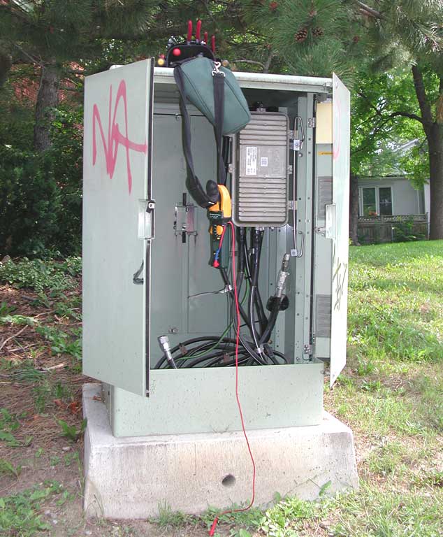
Cable technicians use expensive diagnostic testers built specifically for the CATV industry. This technician's tool belt is on top of the cabinet, along with his tester (the case is hanging over the edge of the cabinet). Typical tester capabilities include measuring noise and signal strength for any channel (that is, any frequency under 1 GHz), and injecting noise or signal.
17 of 46
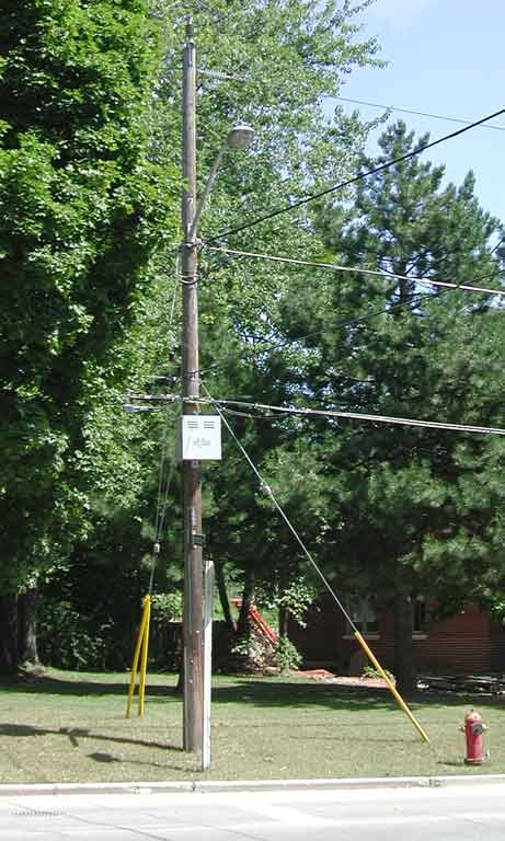
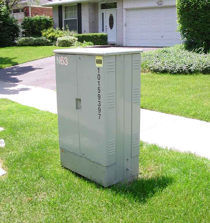
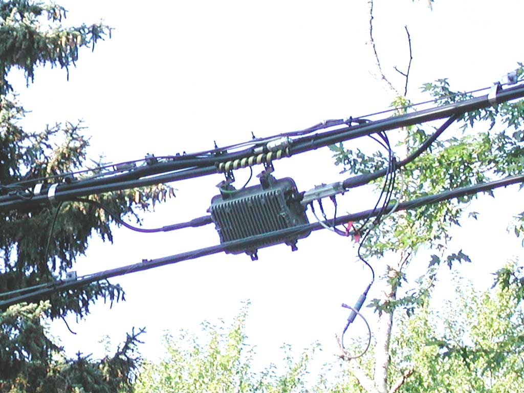
This grey enclosure is a CATV power supply.
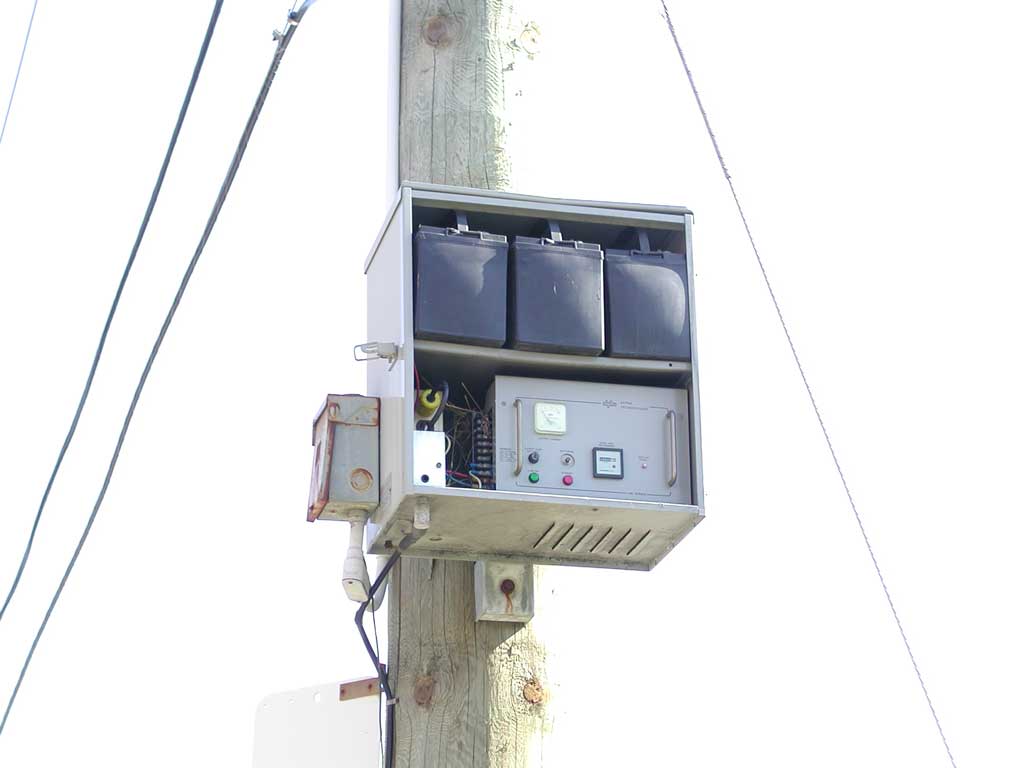
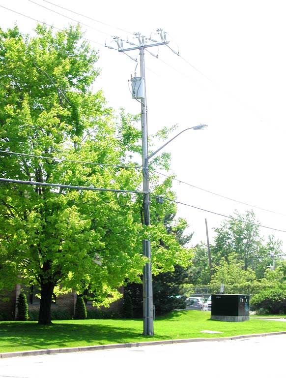
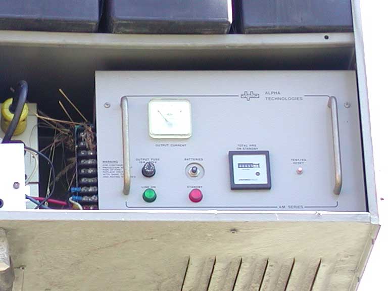
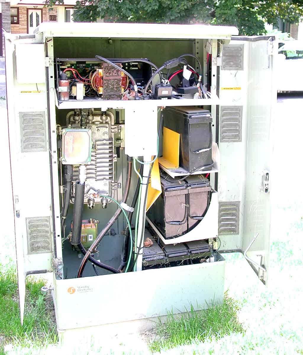
This power supply is missing its door, and is made by AlphaNet Technologies Inc. (a typical data sheet is here), and has both a power supply (at the bottom) and rechargeable batteries (the three things that look like car batteries on the upper shelf). The power supply receives 110 volts AC from the power lines which are farther up the utility pole (and the cable TV company pays the electrical utility for this, based on the number of devices installed – there is no power meter as you have on your house), and converts this 110 volts AC to 60 volts AC (though newer cable TV systems use 90 volts).
In the early days of cable TV, the system only provided signals to televisions, so if there was a local power failure and the amplifiers stopped working, people wouldn't have television (and the televisions would likely not be working due to the power failure anyways). Therefore, rechargeable back-up batteries were not used in early cable TV systems.
But now cable TV systems are used for other purposes, such as cable telephony, so is providing communications for people's home telephones (which are expected to work during power failures), these power supplies have rechargeable batteries that can provide power for a few hours during local power failures.
19 of 46
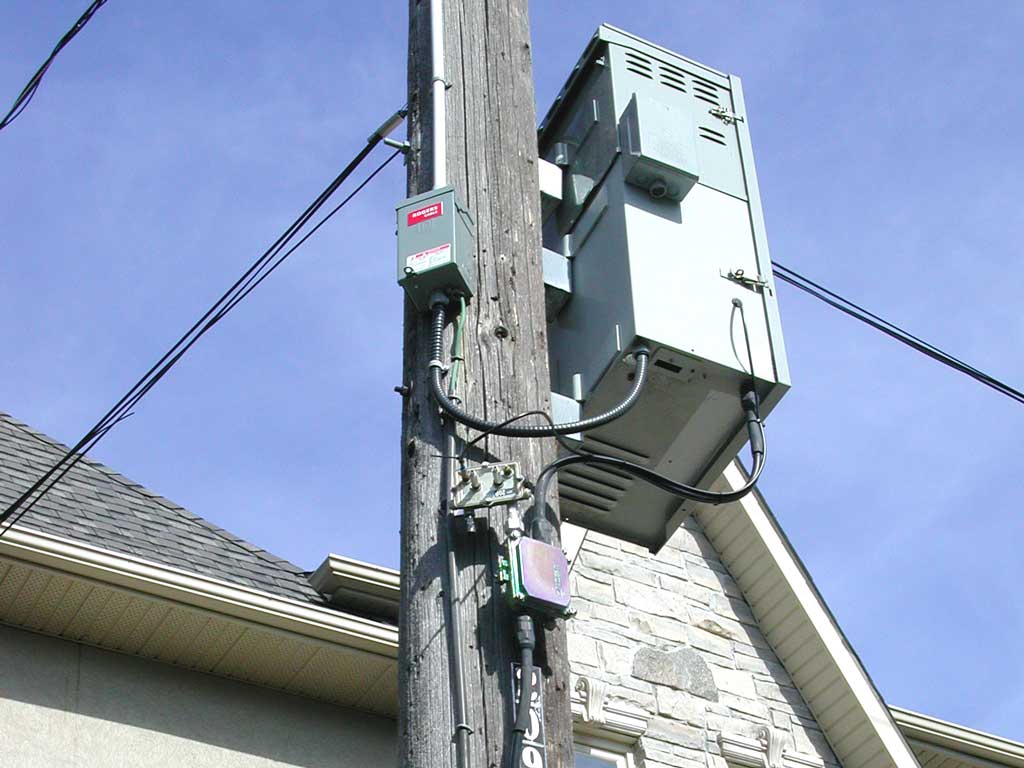
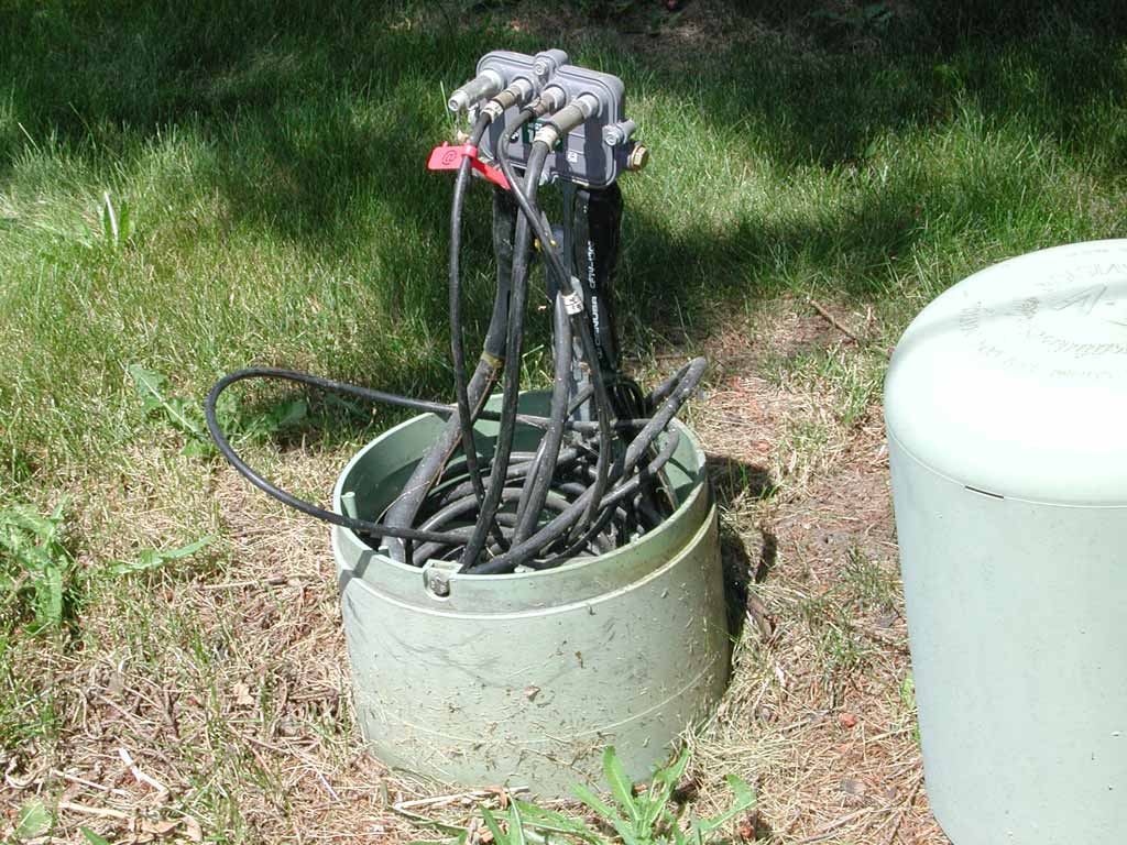
As you can see in the picture below, these cabinets usually have additional batteries contained in expansion chassis which have been added to increase their capacity (so they can power more equipment, such as reverse channel apmplifiers in the trunk amplifiers, for longer). Power supplies which do not have expansion chassis are often abandoned (you can check this for yourself by looking at whether the cables below it are disconnected), and this function is done by a larger ground-level cabinet.
In fact, as you look closely at CATV infrastructure, you'll see much abandoned equipment (unused cables and power supplies are common). Since the cable TV company pays a flat rate for pole rental, they have no motivation to remove old equipment (which would just require more time, and then create a need to properly dispose of harzardous waste, such as the lead-acid rechargeable batteries). Such abandoned equipment just makes more visual pollution, and since most people don't realize it isn't needed, it will grow to be a worse problem as technology advances, and more equipment is abandoned.
20 of 46
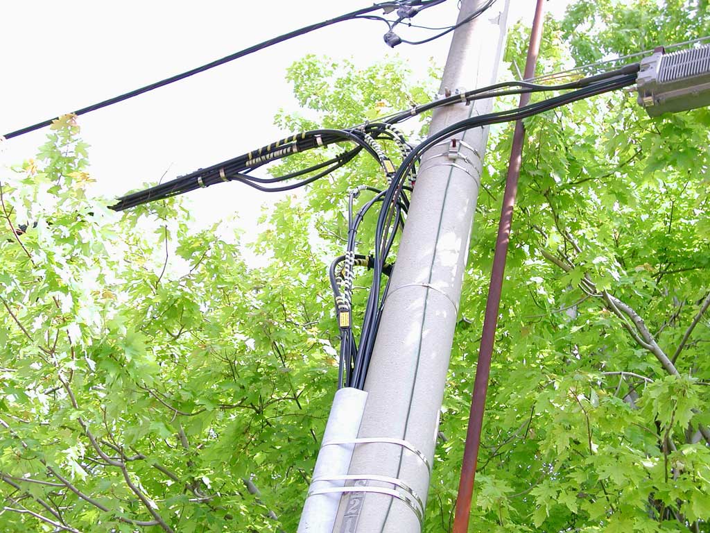
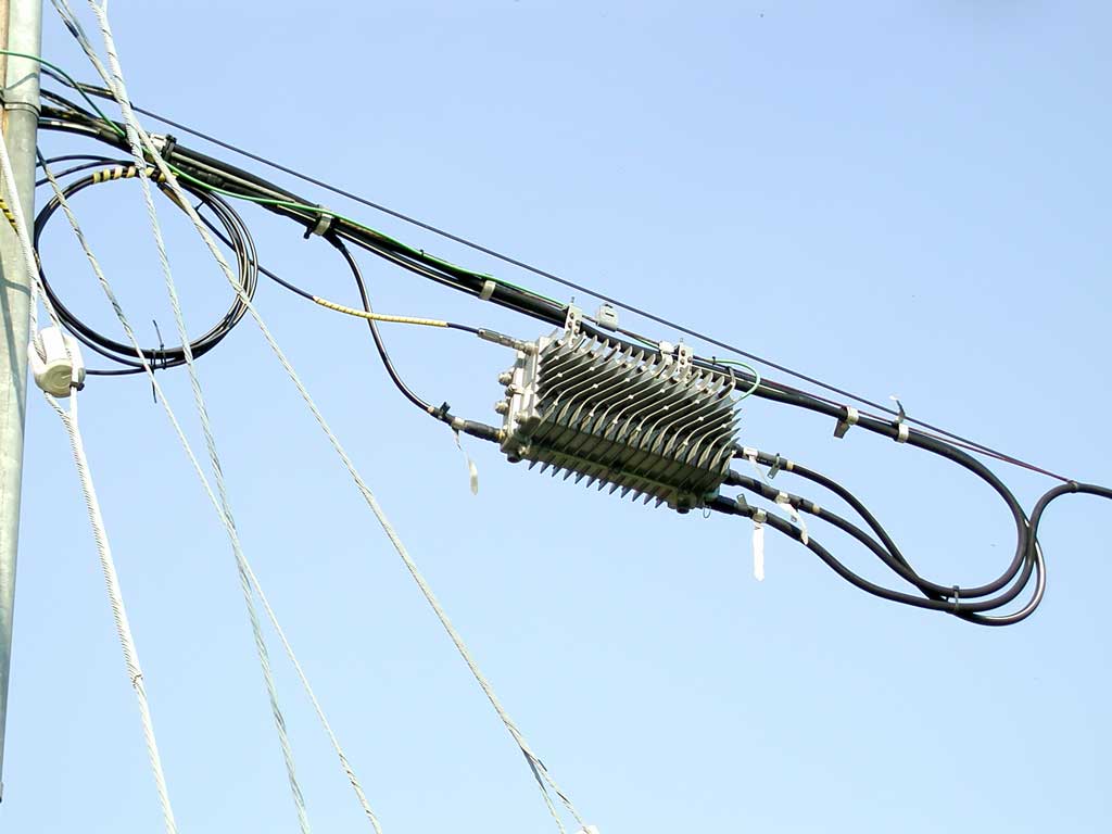
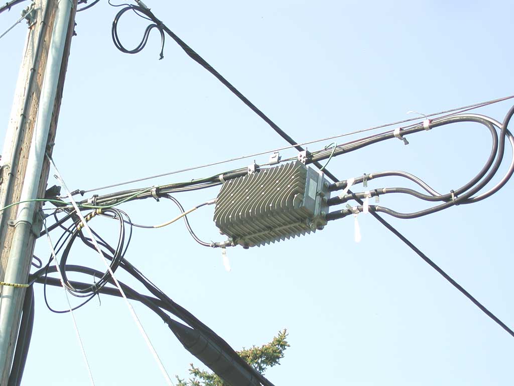
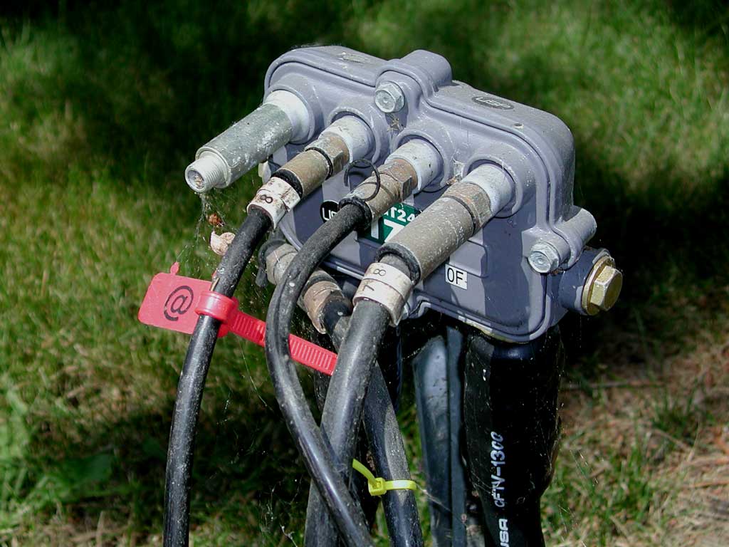
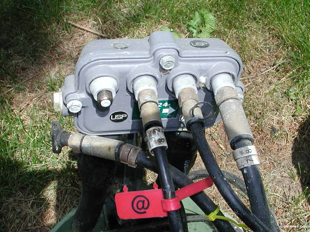
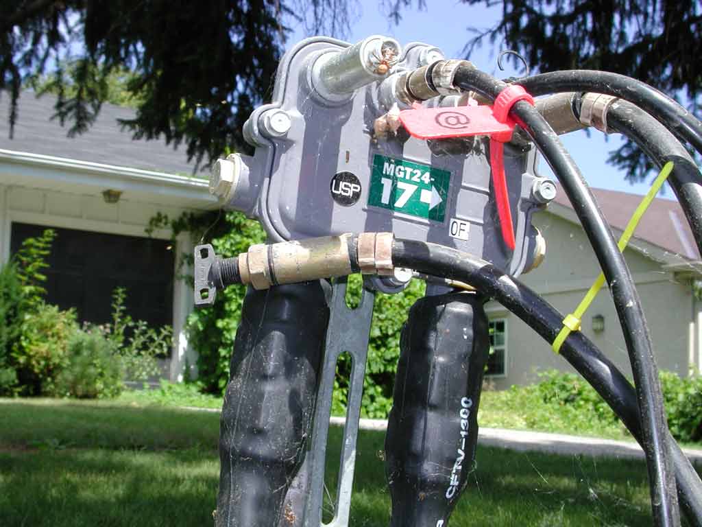
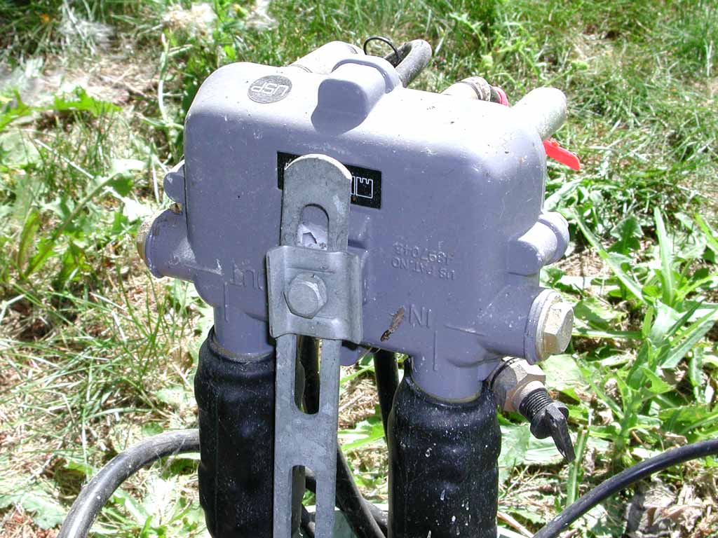
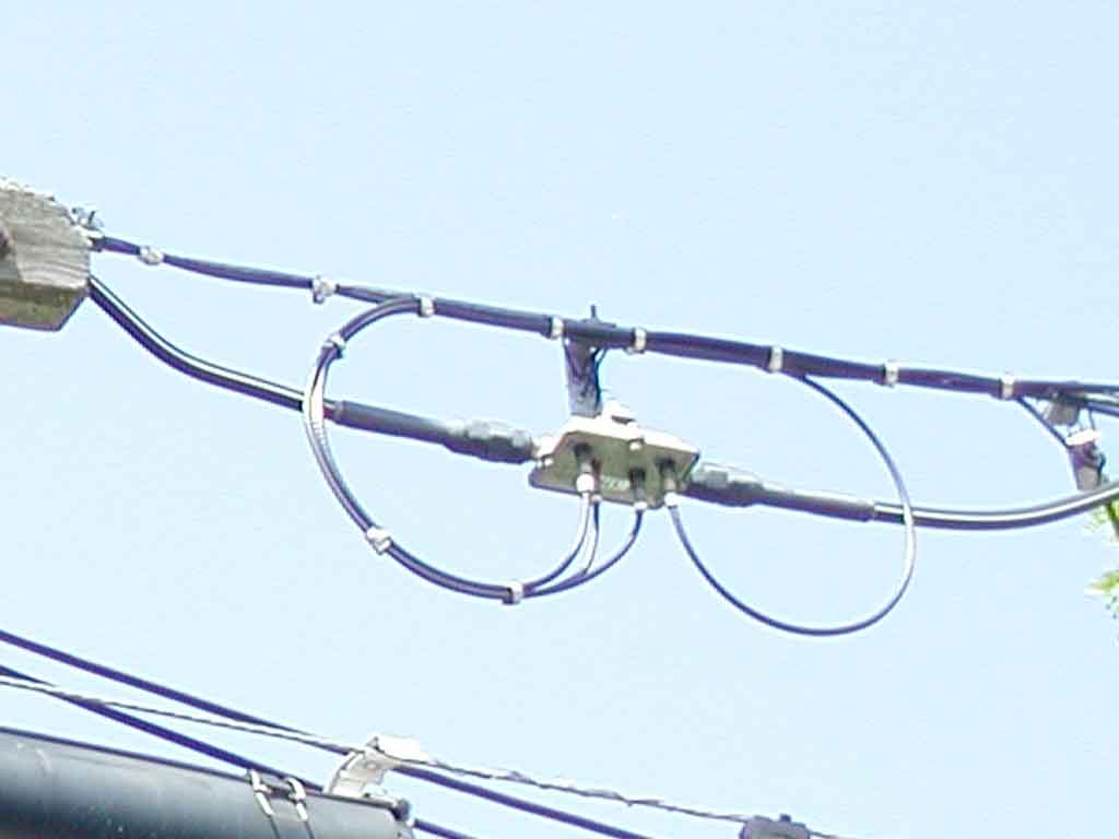
The power coax feeds power into the trunk or line (running down the utility pole) through a Lindsay Electronics LHI 100 Power Inserter (which looks like a directional coupler).
The third port of the Power Inserter is connected to a tap. This tap has four F-type ports (the same type as on your television), and the downstream port has a terminator (since it does not continue on. This tap has terminators on two of the four F-type ports (it should have one more).
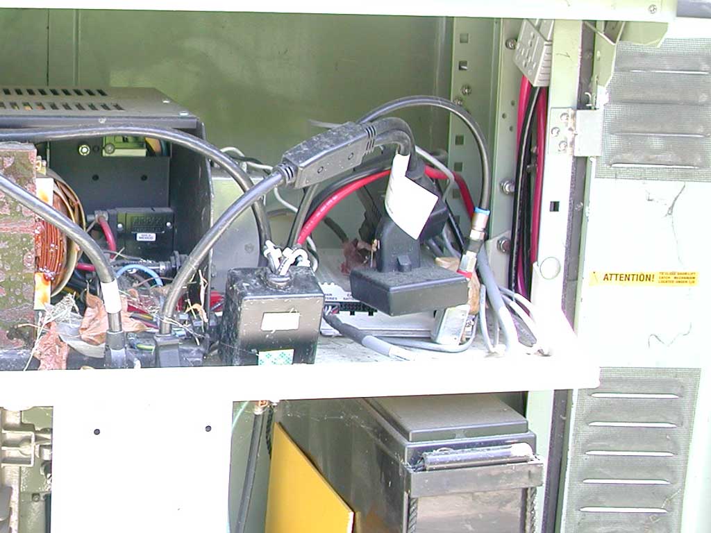
The whole reason for this coupler and tap being installed is the one thin coaxial cable which runs back into the power supply. Inside the power supply, this thin coax is connected to a status monitor, such as an AlphaNet Technologies Inc. XP-EDH-A External DOCSIS Transponder (the manual for it is here).
The status monitor is about the size of a paperback book. It has many connectors, and through these can monitor; the voltage of each string of batteries, the temperature, whether there is a local power failure, and a tamper switch which detects if the power supply cabinet door is open. Using standard TCP/IP and SNMP (simple network managment protocol, as is common for remote network management), this information is made available to a network management system at the cable TV company's head-end through a data connection which works the same way as the cable modems which carry Internet traffic. That is, it receives data using a small range of frequencies between 5 and 52 MHz, and sends on a 6 MHz channel between 91 and 857 MHz (approximately channels 37 to 133).
While this power supply is pole-mounted, as shown in the picture below, power supplies can also be integrated into trunk cabinets.
21 of 46
In the lower section of this cabinet, there are a total of six 12-volt rechargeable lead-acid type batteries on the right side. The LHI 100 Power Inserter is at the bottom, and the thin coaxial cable is connected at the bottom, loops up along the 110v plastic conduit supply cable until it curves back down to the status monitor at near the top-right (there's a close-up of this below).
The trunk amplifier is on the left, at the back. The LHC 108 directional coupler is in front of it.
23 of 46
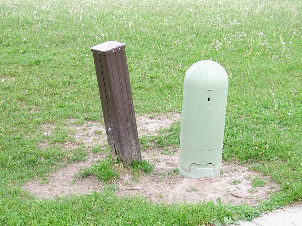
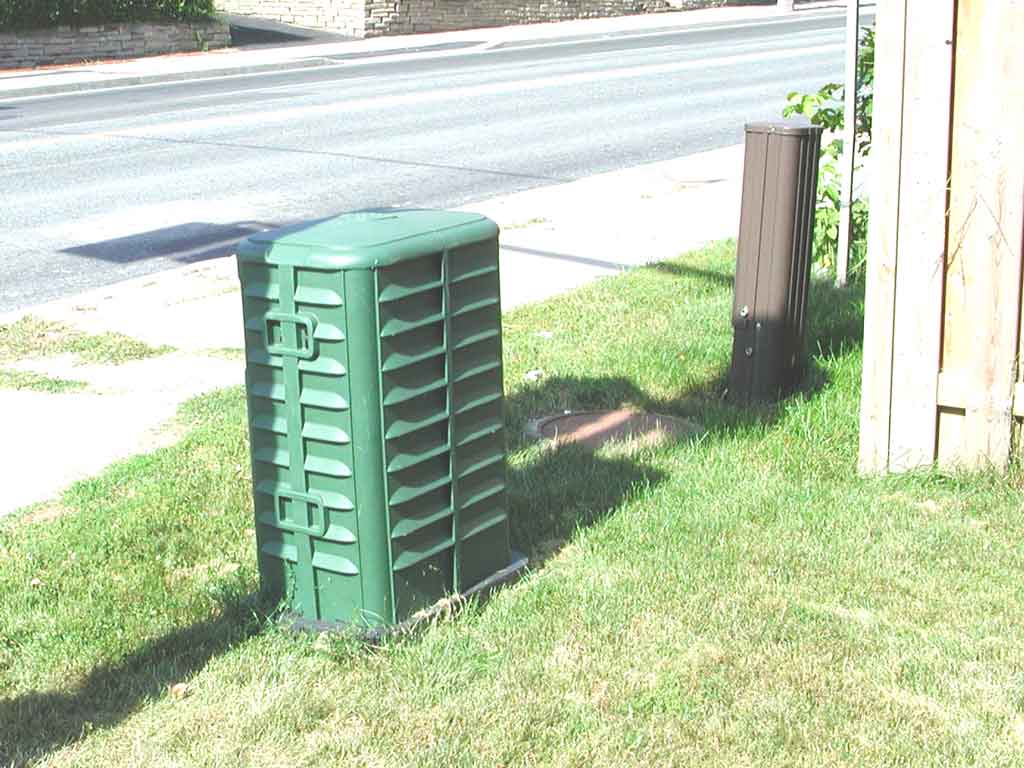
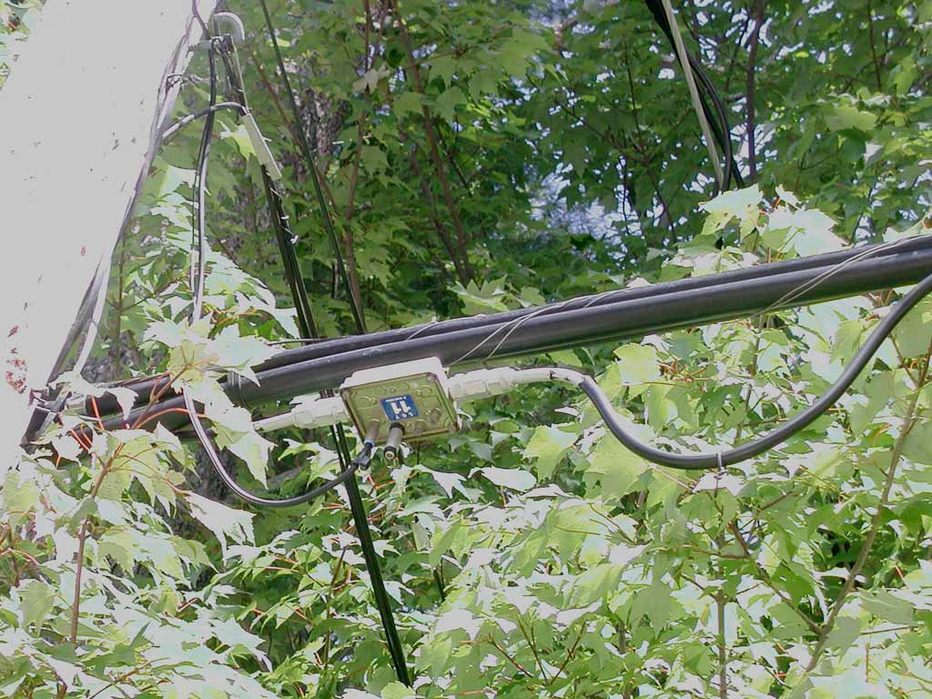
The brown enclosure on the left is a telephone company terminal. It taps into a 50-pair telephone distribution cable running down the street and feeds the telephone drop cables into people's homes.
The green enclosure on the right houses the cable TV distribution line extender. A data sheet on this enclosure (which is made by Channell Commercial Corporation) is here.
25 of 46
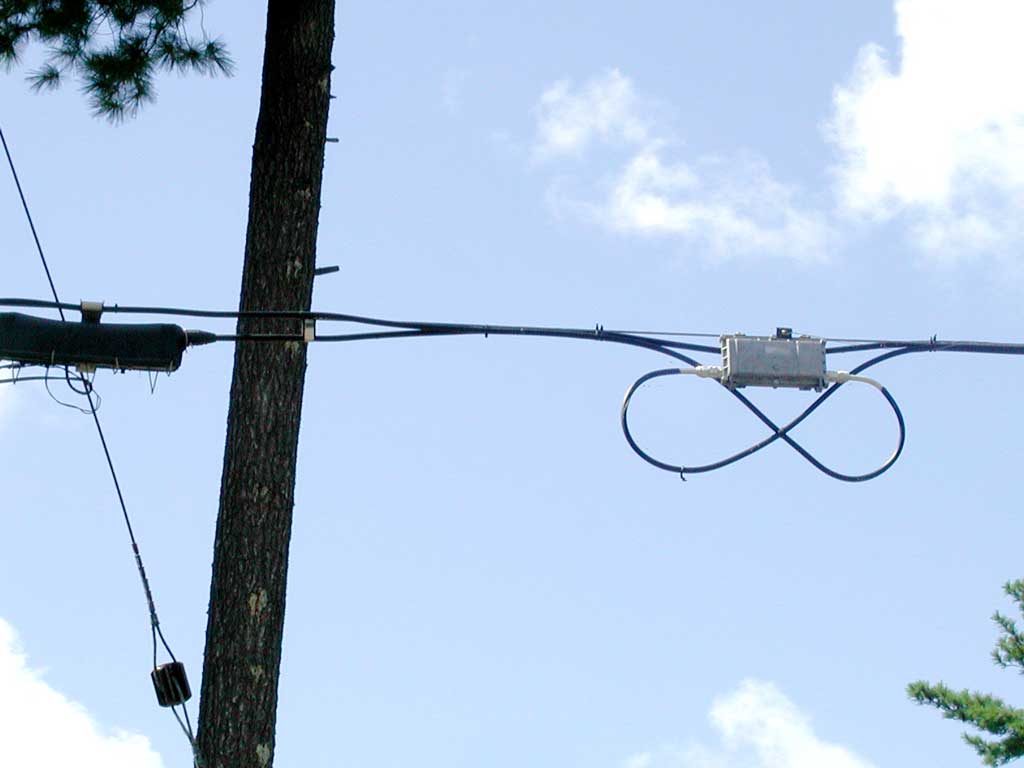
Mounted on the vertical bracket is a cable TV line extender. It is like a trunk amplifier in that it bi-directionally amplifies the signal on the coaxial cable, and is powered from the 60 v AC power on the same coaxial cable. But the coaxial cable is thinner, the signal levels are lower, and generally, line extenders have only a single output. Often there will be a tap in the same enclosure to provide F-type connectors to connect to the coaxial cable which then runs directly to nearby homes. A data sheet for a newer line extender than this one is here.
26 of 46
Typically there is a line extender every four or five taps – the design is usually done by a computer program, which knows the type of cable installed, requirement to keep the length of the cable from the tap to people's homes less than 150', frequency range to be supported, and other factors).
We'll talk about that trap (the cylinder in-line on the hanging cable) after the next few pictures.
27 of 46
This particular 4-port tap is made by from Antronix Inc. Some technical information is here.
29 of 46
Each of these four ports has all the analogue cable TV channels fully available to anyone that connects to them (some might be tempted to run their own cable, and not pay for the service). These four-port taps are installed every four houses, so that if all the nearby houses subscribe to cable TV, then all ports will be used. But if some houses don't subscribe to cable TV, then there will be unused ports to which people could illegally connect (it is called theft of telecommunications services), and the cable TV company doesn't want this to happen (also, unused ports can allow noise into the cable plant and also create signal distortion due to reflections from the unterminated port).
To prevent all these nasty possibilities, cable companies install a terminator (which is basically a 75 Ω resistor) is screwed onto unused ports, as these will prevent outside noise from entering the cable plant, and eliminate reflections. To prevent unauthorized people from removing these terminators, some companies have developed locking terminators, which require a special tool to remove.
On the left port is a Gilbert Locking Terminator. This was developed by Gilbert Engineering (which has since been bought by Corning, so is called Corning Gilbert, at http://www.corning.com/CorningGilbert). If you try to unscrew it (by turning the barrel, or even the F-type threads on the near end), you'll find that the cylindrical body just rotates freely, and it does not unscrew anything. A data sheet on this device is here. It has a picture of the tools they make for removing the locking terminator. Their Terminators and Accessories catalogue also shows the locking terminator (here), and their Tools and Miscellaneous Products catalogue (here) also lists these tools.
30 of 46
A plug has been screwed into the unused male connector to keep moisture (which will corrode the center wire) and bugs out of it.
31 of 46
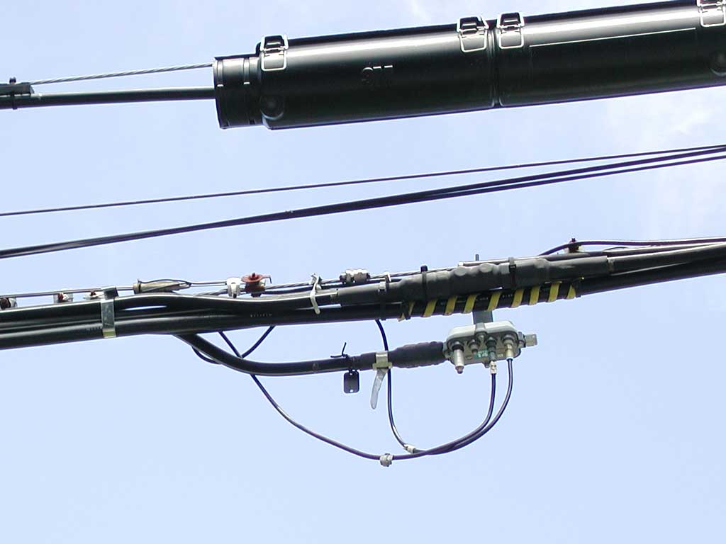
This tap can pass up to 12 amps on the distribution line, to pass power, inserted by a power supply on the distribution line on one side on to line extenders on the distribution line other side.
The heat-shrink tubing over the distribution line connectors on the bottom keeps moisture out.
32 of 46
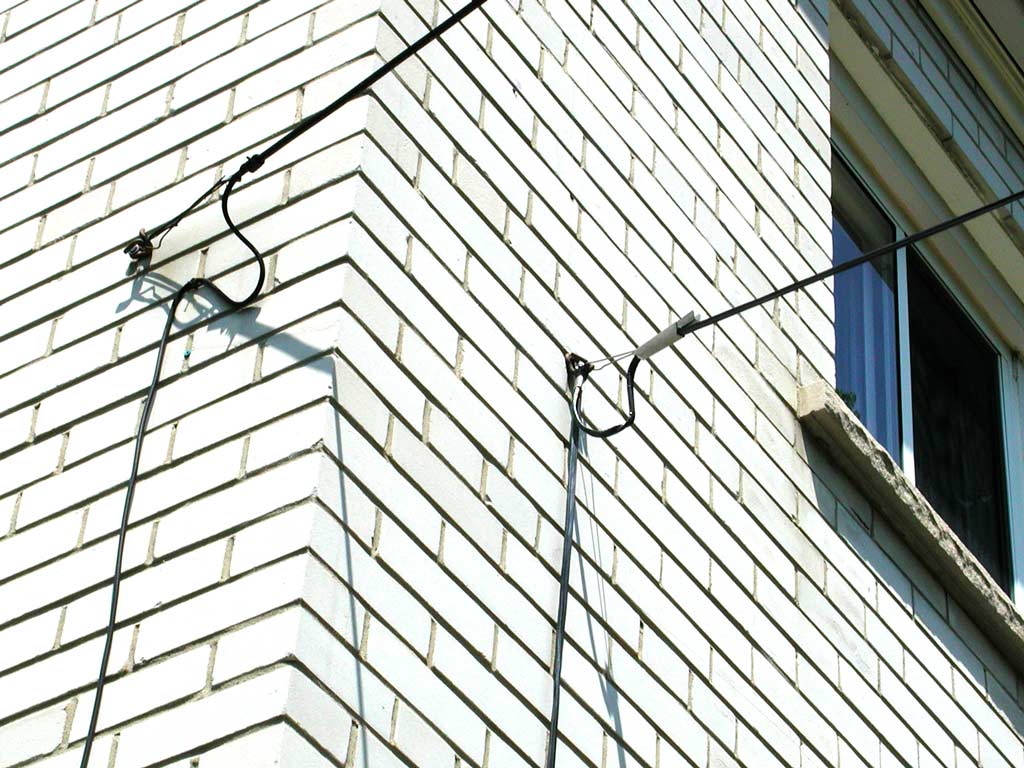
This properly done installation has cable ties to keep everything neat, and ensures the cables are not bent too sharply.
34 of 46
Also, here you can see that there are drop cables attached to only the right two F-type connectors, but only the left unused F-type connector has a Gilbert locking terminator (there should be another terminator on the unused port to the right of it).
36 of 46
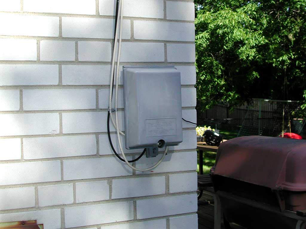
Some cable companies charge more for additional cable TV outlets in the home, and don't want their subscribers messing with the cables, as the signals may be degraded if poor quality cables or splitters are used, or if too many outlets are added or the connections are not properly made. Therefore, these demarcation boxes are often locked.
38 of 46
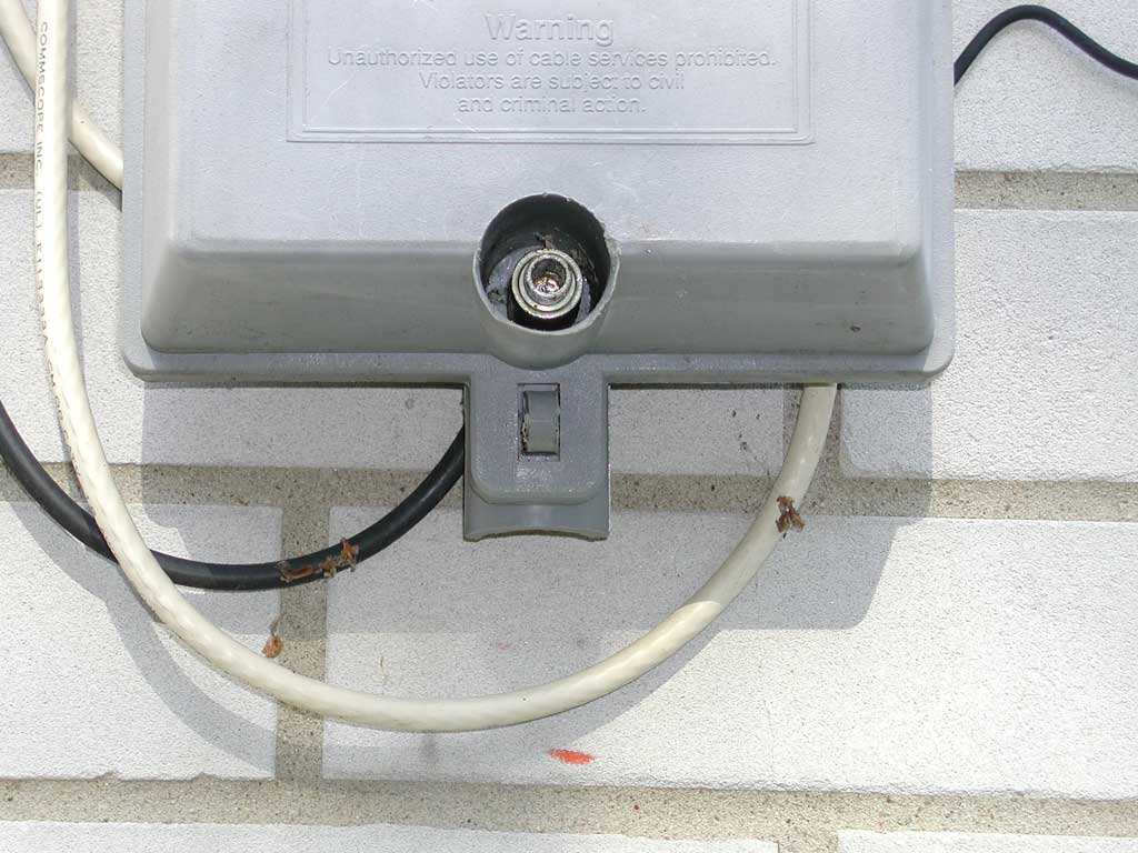
Instead, a Gilbert locking terminator is used – not for the 75 Ω termination it provides (as shown in the catalogue above, these can be ordered without resistors), but for the fact that a special tool is required to remove it. So in this case, the locking terminator ensures that the customer cannot open this demarcation box. If you try unscrewing this locking terminator, it just rotates freely, and nothing unscrews.
39 of 46
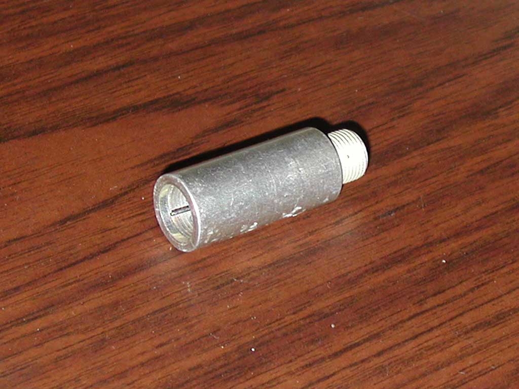
It looks like a short extension for an F-type connector, male on the left, female on the right. As mentioned above, if you try simply turning the outside of the barrel, or even the female threaded end at the right, it just spins freely, and does not unscrew the threads on the left. So, when this is screwed into the bottom of the demarcation (with the special tool), turning the barrel or the end (which is all you can get at) doesn't unscrew it, so you need the special tool to open the demarcation.
40 of 46
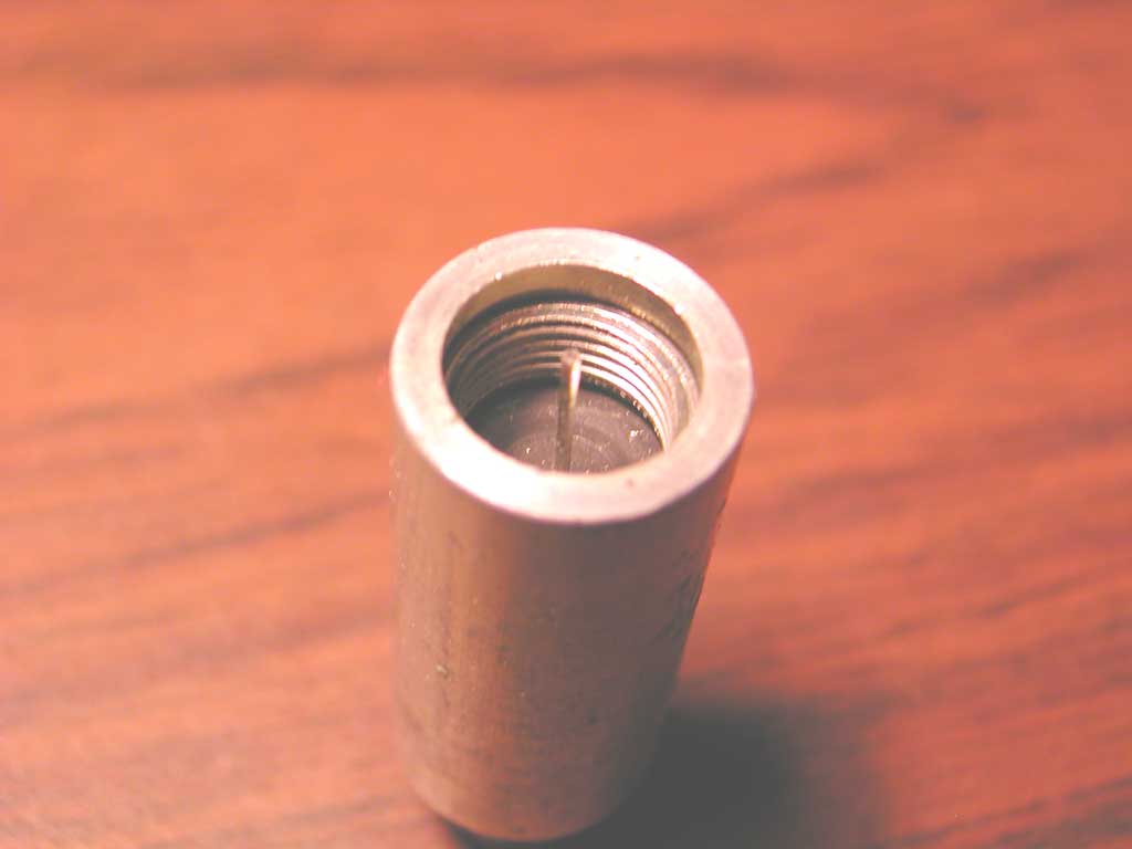
The top half of this cylindrical opening is attached to the outside of the barell, but the lower half (starting at the top of that slot) is separate, and is attached to the threads at the male end.
So to unscrew this locking terminator, you need a tool with a shaft that slides into this cylindrical opening, and which has short (less than the length of those slots) spring steel blades (they call them “ears”) that expand into these slots when the tool is pushed into the cylindrical opening.
42 of 46
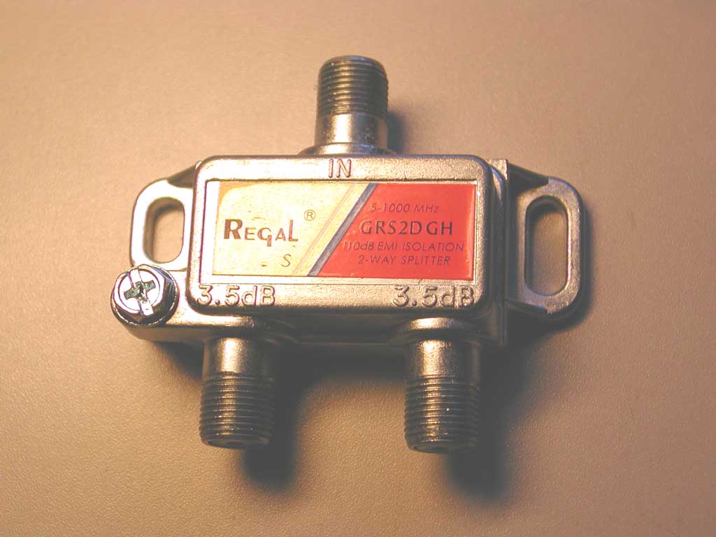
If there is more than one (other than the input) cable coming out of the demarcation box, then a signal splitter is needed, and here is one with one input and two outputs (all with female F-type connectors).
It has a metal enclosure, to keep out electrical noise, and has provision (the screw at the left) to attach a ground wire, to provide even better noise immunity.
The top connection is where the input (from the cable TV company) goes, and the two outputs are at the bottom. This is a passive device, in that it does not use power, so cannot amplify the signal. If the input signal gets split into two outputs, then (for a two-port splitter) each output can have (at the most), half of the input signal strength (in practice, the outputs have slightly less than half the input, due to losses in the splitting process).
When working with signal gains and losses, it is often helpful to work in decibels (abbreviated dB), which are named in honour of Alexander Graham Bell (but a Bel is too large a unit for typical applications, so a tenth of a Bel – a decibel – is typically used). If the output has half the input signal strength, it is approximately 3 dB “quieter”, so the 3.5 dB attenuation (as marked on the enclosure) at each output port accounts for the extra loss due to the splitter.
43 of 46
For analogue cable TV, the cable company has to send all channels to everyone. But if the cable TV company wants to offer different tiers of service, they need to block the channels from users who are not paying for them.
To do this, the cable TV company installs this trap in-line with the drop cable. Since removing this device (and directly connecting the drop cable) will enable the customer to get all of the analogue channels (and the cable TV company cannot remotely determine whether a trap has been illegally removed), the cable TV company will usually install these traps in the demarcation box (which they then secure with a locking terminator to keep customers from opening the box and removing their trap).
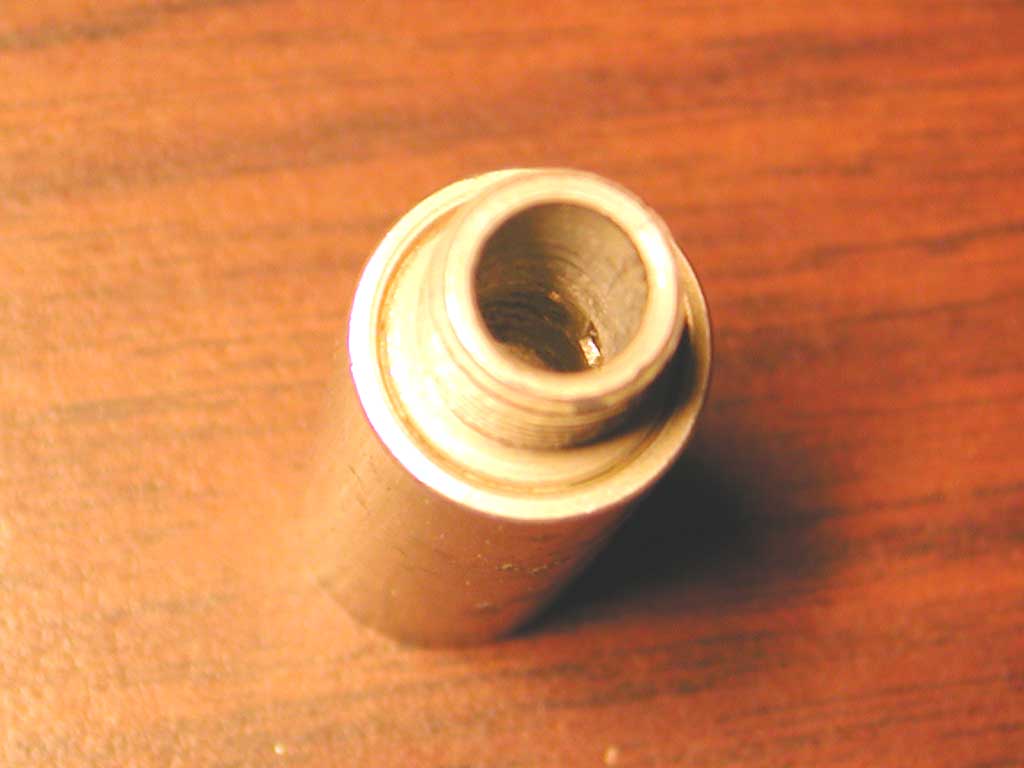
This view shows that the trap has a standard F-type male connector at one end.
44 of 46
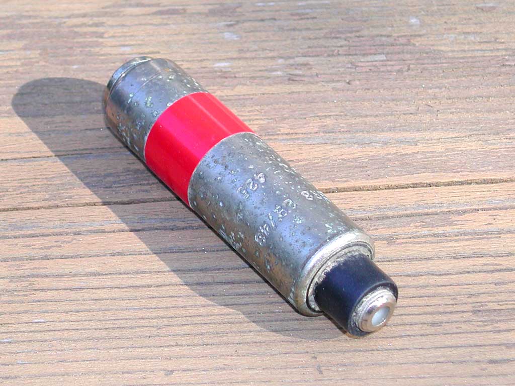
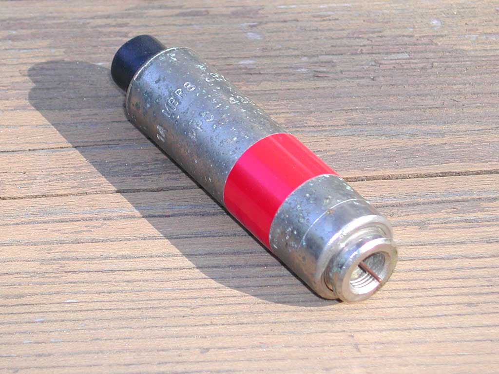
The red tape is installed by the manufacturer, and indicates the range of frequencies (which correspond to a range of television channels) the trap filters. The filter may be a low-pass filter, which prevents all higher channels from passing, or it may be a notch filter, which removes some middle channels, but allows the lower and higher ones to pass. The cable TV company arranges their tiers of channels so the extra-cost channels are in a contiguous block.
The stamping indicates that this one is made by PPC (originally called Production Products Company), is a model MBR-8, and filters channels 29 through 48 (inclusive). The manufacturer's web page for these products is at http://www.ppc-online.com/products/trap_line, and some technical information for a similar (but newer) model of trap is here.
45 of 46
The black solid conductor wire (to the green screw at the left) is a ground wire, which provides both safety (in case a power cable was to accidentially touch the coax) and for lightning protection.
46 of 46
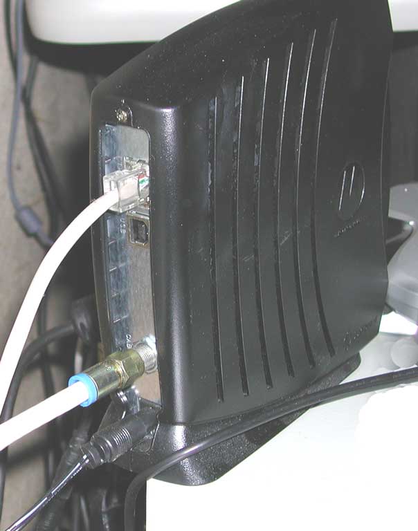
In the above photograph you can see the power input at the bottom, the coaxial cable from the cable TV network above that, and an Ethernet connection for the customer's PC or home network at the top.
While most diagnostic and administrative functions are remotely controlled by the cable TV company (through the coaxial cable connection), this cable modem has a built-in web server which provides some diagnostic information on the LAN interface at http://192.168.100.1. This information includes the: