Directional Drilling
Image 1 of 35
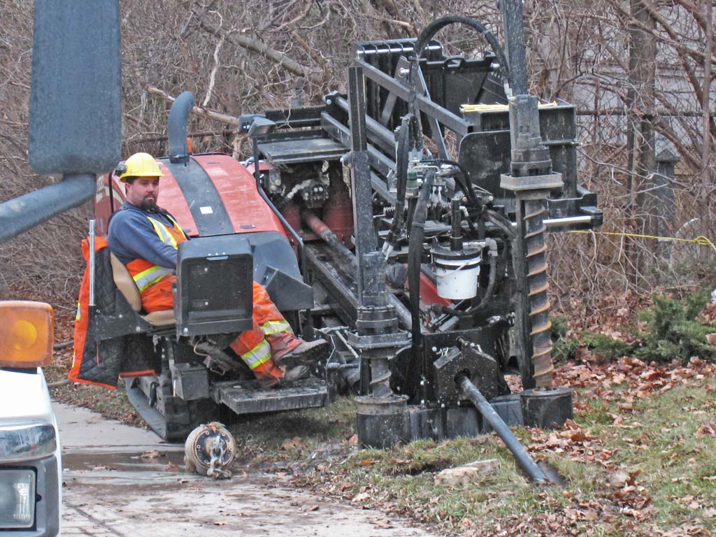
While fibre optic cables can be run aerially (on utility poles, typically lashed to a galvanized steel messenger wire), here the project is to bury a heavy plastic conduit (also called duct) through which fibre optic cables will be pulled.
The traditional method to bury cables is to first dig a trench, and then lay the cable (or a conduit for it) into the trench. Another method is to directly plow the cable into the ground. These methods mess up peoples' gardens and driveways, so they upset taxpayers and have the additional costs of restoring the gardens and driveways.
Therefore, trenchless methods have been developed, and here we'll discuss horizontal directional drilling (or boring).
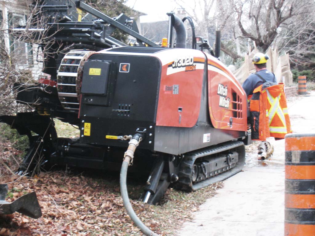
This is a Ditch Witch JT3020 Mach 1 trenchless directional drilling machine, made by The Charles Machine Works, Inc. of Perry, Oklahoma.
But, before the digging (which is quite complex itself), there are several steps.
Image 2 of 35
The first step is to have a utility locate done, to mark the locations of underground services such as water, sewer and gas supply lines and mains, and power and telecommunication cables. The yellow paint indicates gas service and the blue is water service. Since the conduit needs to be installed parallel to the sidewalk, it will need to cross all these gas lines (some fancy technology is used to ensure that nobody gets blowed up).
Image 3 of 35
The drawings maintained by municipalities and the locate services (which use metal and signal detection methods) only indicate the path of the underground services, not their depth.
To determine the depth of these gas and water supply lines requires measuring the depth by hand. Traditionally this required (careful) hand digging with a shovel. This new method is to use a vacuum excavator (that would be this blue truck).
Image 4 of 35
This is basically a large vacuum cleaner that can suck up dirt and small rocks (through the hose beside the gentleman's head) into the large cylindrical vacuum tank on the back of the truck.
The large suction hose coming down from the swing-arm is lowered to the ground, and it sucks big-time.
To help loosen-up the dirt, high-pressure (thousands of pounds per square inch – similar to a high-pressure washer as you might use for cleaning your driveway) water from a nozzle on a long hand-held wand is used. The smaller tanks behind the truck's cab are the water tanks for this.
Image 5 of 35
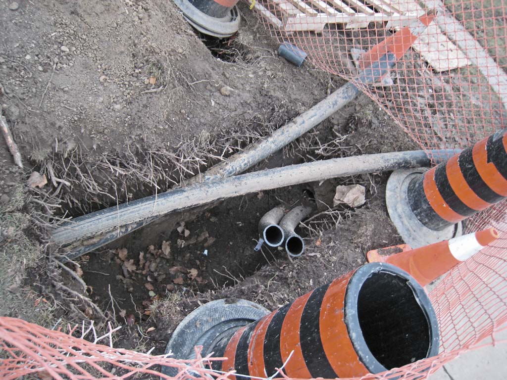
Here we're looking down at my stylish and sensible Rockports, size 9½ – and in front of those you can see a typical excavation. Typically the water and gas lines will be near each other, as a single trench would have been dug for both, a long time ago.
- The blue curb-stop has a small plug in the centre (to keep the dirt out) which can be unscrewed and a long handle can be inserted to shut off the water supply to the house – the pipe leading down several feet ends at the water supply line (in the water at the bottom of the excavation) and its shut-off valve.
- To the left of that (and not as deep) is the gas supply line. Since the vacuum excavator only uses high pressure water and vacuum, there is no danger of damaging the gas line – and it is much easier than hand-digging with a shovel (and much less work).
Image 6 of 35
Here's another excavation, you can see the gas supply line at the very bottom. The pipe only needs to be exposed enough to confirm it is the gas line, and to measure how far below grade it is.
Image 7 of 35
Once the depth of the pipe has been measured, the excavation is filled-in (here with concrete).
Image 8 of 35
It seems a shame to mess up the nice patterned concrete (the filled-in excavation is below the safety cone) just to measure the depth of a pipe.
Image 9 of 35
Here's the Ditch Witch horizontal directional drilling rig (check out the brochure) in position.
The two rear stabilizers help keep the rig in position.
Note the hose bringing drilling fluid to the drilling machine (it comes from an adjacent truck, in which there is something like this), which pumps it through the centre of the drilling pipe (the drilling rig has a pump to boost the drilling fluid pressue up to 1,500 psi). Drilling fluids have many purposes, such as to cool the drill bit and wash away the cuttings from the drill bit.
Image 10 of 35
The levers at the back are for controlling the rear stabilizers and the tilt of the machine (the Operator's Manual is here). Beneath the cover to the left are the controls for starting and moving the machine.
Image 11 of 35
Since the rotating drill bit would cause the entire drilling machine to rotate (and the thrusting action required would cause the machine to push back) a powerful anchoring system is implemented with the two helical screws at the front, which are driven by the hydraulic motors above them (note that in Image 1, only the left anchor is driven into the ground, as that is all that would be needed when the drill bit is turning clockwise). At the right is the pipe box which holds the drilling pipe (either 24 or 48 sections, depending on the size of the pipe box).
Image 12 of 35
Here you can see the other side of the pipe box, and below the pipe column are the two pipeloader shuttles move the bottom pipe between the pipe box and the carriage.
Image 13 of 35
Here is the Operator's view of the two pipe wrenches (just to the left of the anchor screws, and with the pipe across them) which clamp the underground pipe to keep it from rotating when a new section of pipe is to be attached or removed.
Image 14 of 35
Here you can see the pipe gripper on the front pipeloader shuttle. To add a pipe (each is a few inches less than 10' long), the gripper selects the bottom section of pipe from the column and rotates to the right to lower the pipe to be screwed onto the pipe already in the ground.
Image 15 of 35
Here is the thread on the drill pipe. Note that it is tapered so it quickly engages all threads, to reduce the time needed to connect and disconnect pipe sections.
The drilling machine has a built-in pump which the operator uses to ensure that the copper-based lubricant (which prevents rust and reduces wear on the threads) covers the pipe threads and shoulder. The pipe is hollow so the drilling fluid can be pumped downhole to the drilling bit.
Image 16 of 35
Here is the control console to the Operator's left. These indicators are mostly for starting and monitoring (coolant temperature, oil pressure, tachometer, voltmeter, fuel level) the engine. The switches are mostly for manually controlling the pipe shuttle, wrenches and lubricator.
Image 17 of 35
It doesn't seem to be covered in the manual, but to the left would appear to be a coffee cup holder.
Image 18 of 35
The right control console is all about the drilling. The circular gauges across the top show the drill pipe rotational torque, the thrust force, and the drilling fluid pressure.
Above those gauges are indicator lights for the hydraulic fluid temperature, pipe shuttle and carriage home limit switches, and wrench and fluid pump status.
The near LCD below the gauges shows the:
- Gallons per minute of drilling fluid being pumped.
- Drill pipe revolutions per minute.
- Pipeloader status.
- Number of pipe sections available.
- Current drilling mode.
- Whether communications is established with the electronic beacon (which is mounted in the beacon housing which is just behind the drill bit).
- Operating hours and drilling history.
The far LCD shows information received from the tracker (see below). This includes drill slope (to 0.1% resolution), beacon temperature and battery status, the location of the tracker relative to the beacon, the current drill bit rotational position (to 30° resolution) and depth (to 1" resolution). It also has an RS-232 port which can be connected to a laptop computer running software which displays and stores the drill path and the other parameters.
Image 19 of 35
The red button shuts off the engine.
The joystick is used as follows:
- Moving it to the left rotates the drill bit clockwise, which is the normal drilling direction (to the right rotates the drill bit counter-clockwise, which would be used to unscrew the drill pipe or bit). This seems backwards, perhaps it is to be consistent with some industry convention or predecessor equipment.
- Moving it forward applies thrust to the drill pipe and bit (and to the rear moves the carriage backwards, to retract the drill pipe and bit).
- Buttons on the joystick control the pumping of the drilling fluid.
An arm-rest reduces Operator arm fatigue.
Image 20 of 35
Here's the key to the whole operation – the value of directional drilling is that the drilling Operator can control the direction of the drilling (generally to avoid obstacles such as gas lines, but also for other situations such as drilling under rivers). This electronic guidance provides the information needed to know exactly where the drill bit is.
This person is holding a tracker, which receives a signal from the electronic beacon which is in the drill string just behind the drill bit. The information on the display shows him where he is relative to the drill bit, so he can walk directly above the drill bit (he therefore has a keen interest in ensuring the drill bit doesn't chomp through buried gas lines). Knowing the depth of pipes and obstacles to be cross, and seeing (on the display) the current depth of the drill bit allows him to communicate (with his walkie-talkie) to the drilling Operator required changes in the drilling direction.
Image 21 of 35

Drill bits are often made by specialty companies, and the drill bit is not symmetric – it is more like a flat blade which is bent outwards. So long as it is rotating, it will drill straight (maximum rotation speed is about four revolutions per second, but is typically one or two revolutions per second). When a change of direction is required (because the guy above the drill bit sees that the next gas line is at the same depth as is the drill bit) the Operator slows the drill bit rotation and watches the roll indicator display to stop the drill bit rotation with the bit pointing towards the direction desired. The Operator then thrusts (with up to 24,000 pounds of force) the drill bit forward (which will then follow the direction of the bit), and then resumes rotation.
Image 22 of 35

The conical shape and the channels and teeth allow the back-reamer to be pulled back through the hole just bored, and the holes allow the drilling fluid out to assist with packing the hole tight so it does not collapse. The U-bolts at the end are attached to a clamp attached to the conduit, which is then pulled back through the hole to the drilling machine.
Image 23 of 35
Here we can see two conduits which have been so pulled back through the bored hole.
Image 24 of 35
Here the two conduits on the right will be spliced (using the cylindrical fitting near the top centre of the picture) to the two conduits on the left (which will be cut back as required).
Image 25 of 35
This shows the substantial thickness of the conduit wall. This is required for strength (both when pulling the conduits back through the bored hole and so it won't collapse from the weight of the earth above). The glove is there to show the size (I didn't have a ruler with me at the time). The inside of the pipe will be very smooth to reduce the friction for later pulling the fibre optic cable through the bored hole. The ridges inside the conduit are only at the end, and are due to the duct pulling clamp (here is another – there are speciality companies that make these products).
Image 26 of 35
Here are two spools of conduit waiting to be pulled into the bored holes.
Image 27 of 35
Looking closely at the conduit shows it:
- Was made in Canada on February 12, 2008.
- Is high-density polyethylene (“HDPE”).
- Has an inside diameter (“I.D.”) of four inches.
- The foot counter is 661 and 637, for the two markers in the picture (this facilitates installers know how much conduit has been pulled).
- The Standard Dimension Ratio (“SDR”) is 13.50, which means that the ratio of the nominal inside diameter to the conduit wall thickness is 13.50 (so the wall would be about 0.3"). Actual HDPE conduit dimensions, tolerances, and strengths are specified in standards such as D 2160, D 2239, and D 3035 from ASTM International (which was previously known as the American Society for Testing and Materials).
Image 28 of 35
When fibre optic cables need to be spliced (for example, to connect one cable to two smaller cables), the conduit will be run to a cable vault, such as this one (which is upside-down, awaiting installation). Note that the bottom is open.
Image 29 of 35
This cable vault is 36" wide and 60" long and has a depth (into the ground) of 36". It has an aluminum cover.
Image 30 of 35
Looking into the upside-down vault, we see some 90° elbows which will be used to bring the fibre optic cables up into the vaults.
Image 31 of 35
Here is a vault installed flush with ground level (with the two-part aluminum cover opened), with fibre optic cable pulled into it (the extra cable allows the splice to be done in a nearby truck).
Image 32 of 35
Stones at the bottom of the vault facilitate drainage and keep the mud down. The yellow spiral wraps indicate fibre optic cable.
One unused conduit has a lightweight polypropylene twine which would typically be blown through the conduit using compressed air – a balloon (also called a shuttle or carrier) on the end of the twine pulls it through. The other unused conduit has a polypropylene rope, which may have been pulled in using the twine, and would be used to pull in the fibre optic cable.
Other methods directly blow the cable into the conduit.
Image 33 of 35
When in service, the fibre optic cable light souce is infrared light (which is invisible to humans) from a powerful laser that can damage retinas, hence the warning.
Image 34 of 35
This fibre optic cable has 864 strands of single mode fibre.
Image 35 of 35
Here is the cable vault, with cover installed. That was a lot of work just to make someone's front lawn uglier.