
Firstly, information is sent through fibre optic cables as pulses of light, so the “ones” and “zeros” that make up the information are sent as combinations of the light being on or off. The actual “colour” of the light is in the infrared (this light has a longer wavelength than red light, and red is the longest wavelength of light we can see, so infrared light is invisible to us – which is why it doesn't have a colour).
The wavelength of light is typically measured in nanometers (millionths of a millimeter), which is abbreviated nm, and people can see wavelengths from about 400 nm (which we see as violet light) to 700 nm (which we see as red light). For fibre optic cables, the wavelengths of light used are typically 850, 1,310, or 1,550 nm, because the fibre optic cable is more transparent (that is, has lower attenuation) to these longer wavelengths (this allows longer runs of fibre optic cable). However, the longer wavelength light sources and sensors are much more expensive, so what usually is implemented is as follows:
An important safety note is that because the light is invisible (and can be very bright), it can damage eyes if one looked directly into a lit fibre optic cable. Therefore, you always see warnings about this on fibre optic equipment.
Light typically travels a different speed in different transparent materials, and this is usually expressed as the index of refraction, which is the ratio of the speed of light in the material compared to the speed of light in a vacuum.
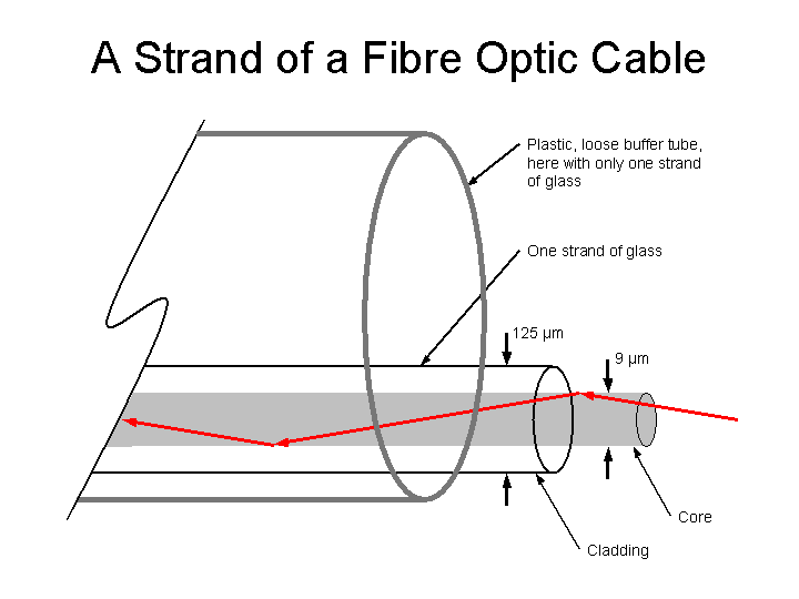
When light changes speed, it changes direction, which is why magnifying glasses work – the light rays bend. A strand of fibre optic cable actually has glass with a sharp increase in the index of refraction at the boundary of the cylindrical core of inner glass, and the glass around that is called the cladding. As shown in the diagram above, when light enters the core (from the end), it bounces (which is called total internal reflection – since all of the light reflects) off the boundary between the core and cladding, and therefore ends up at the far end of the fibre optic cable (which is therefore sometimes called a light pipe).
The fibre optic cable is very thin. The diameter is measured in micrometers (thousandths of a millimeter). The cladding has a diameter of 125 Ám, which is an eighth of a millimeter (actually, there is usually a primary, and even a secondary coating which may make the diameter up to 250 Ám –, but this is still really, really thin. For the single-mode (so called, as there is only one way – or mode – the light travels down the core, so it all arrives at the same time, which is important for longer cable runs) fiber used by carriers, the core has a diameter of about 9 Ám or 10 Ám.
The strand of fibre optic cable is very fragile, and is protected by a buffer tube. This is a somewhat flexible plastic, and is coloured to so technicians can identify each buffer tube in a cable. For the long-distance fibre optic cables used by carriers, where low loss (also called low attenuation) is most important, but the cable runs don't need to have sharp bends, the buffer tubes are a much larger diameter than the strands of glass, and up to 24 strands will be in each buffer tube. This is called loose tube construction (picture several runs of fishing line, lying in a drinking straw).
Now picture what happens if that drinking straw is bent too much – it kinks, and the fibre optic cables inside will be damaged by being bent so sharply. Therefore, for fibre optic cable runs within buildings, where the cable is short enough that attenuation doesn't matter as much, but where sharper bends are necessary for the confined spaces above ceilings and behind walls, a tight buffer fibre optic cable is used. In this case, the buffer is directly extruded onto each fibre optic strand (similar to plastic insulation on a copper conductor), so the fibre can have a smaller bend radius without kinking.
Note that in all cases there is a minimum bend radius, beyond which the cable will be permanently damaged.
2 of 33

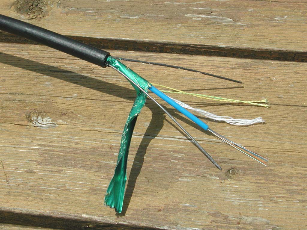
While glass this thin is flexible (just as a thin copper wire bends easily – but thicker metal won't), if bent too sharply, the glass fibre will crack, and if a small piece breaks and you get a sliver, or some in your eye, that is a problem. Therefore, when technicians are working with bare fibre, they should be wearing safety glasses.
This fibre has a tight buffer – which is the white covering at the lower-left.
3 of 33
For optical connections, the goal is to have as much of the light from one fibre coupled into the other.
A permanent electrical connection can be made by soldering wires together, and a permanent optical connection can be made by melting the ends of the fibres together, which is called a fusion splice (this requires an expensive machine).
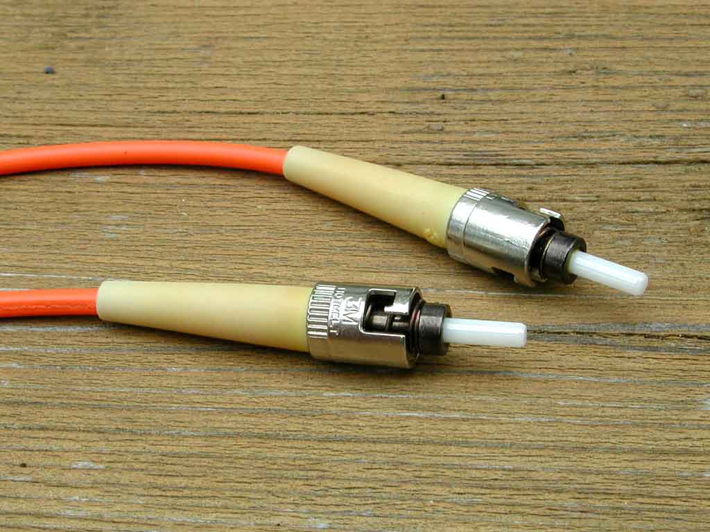
Here is one type of fibre optic connector, called an ST – for “straight tip”, since a predecessor connector (called biconic) used two nesting cones to align the fibres. The locking method used by the ST connector is called bayonet (where you push and turn, so named after the way knives were attached to old rifles). The white tip is a ceramic, which has an extremely low thermal coefficient of expansion (that is, it does not change shape due to temperature changes), so the alignment of the fibres (and therefore the loss through the connector) will not be affected by temperature changes.
There is a small hole running through the length of this ceramic cylinder, into which the bare fibre is placed. The hole is so small, it is barely visible without a microscope.
This type of fibre optic cable is often used for patch cords, where two nearby devices need to be connected (such as in a computer room). Generally, each patch cord will have two fibres (so it is called duplex fibre), one for the transmit data, and the other for the receive data (farther back, these two orange cables are joined, like lamp cord cable).
To identify cables as fibre optic cables (rather than, say, power cables), fibre optic cable jackets are generally orange or yellow. For outdoor cables (which must be black for ultraviolet light resistance), a spiral orange or yellow wrap (which often has a tag identifying the cable's owner) is applied, generally at each utility pole.
4 of 33


If you look through even a few centimeters (such as a few stacked sheets) of window glass, you'll see a greenish colour. This is due to impurities in the glass, but for typical window pane thicknesses, this attenuation of the light isn't a problem.
A fibre optic cable requires the light to go through many kilometers of glass, so the glass used for fibre optic cables must be extremely pure, resulting in much, much, much (maybe even a few more muches) lower attenuation. However, as a result of contamination with water during the manufacturing process, early fibre optic cables had hydroxyl ions (which have the chemical symbol OH–) trapped in the glass, and these absorb light in a range of wavelengths centered at 1,383 µm. This is why wavelengths near the 1,383 µm hydroxyl absorption band were not used in early communication systems.
However, for some applications, such as wavelength division multiplexing (WDM, where the fibre's information carrying capacity is increased by sending information simultaneously at different wavelengths), those absorption wavelengths needed to be used. As a result, manufacturing processes were developed to make fibre optic cables (sometimes called “low-water”, or “low water-peak attenuation”) that did not have significantly greater attenuation in the hydroxyl absorption band. These fibres are called enhanced single-mode (ESM) fibre optic cables (most cables manufactured now are of this type, even if that characteristic isn't needed).
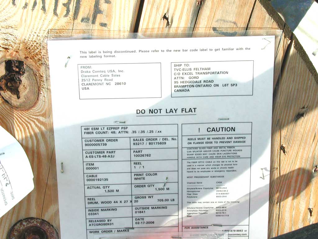
The last long number printed on the cable jacket is for product tracability (such as manufacturing batch number and the factory and line identification).
8 of 33
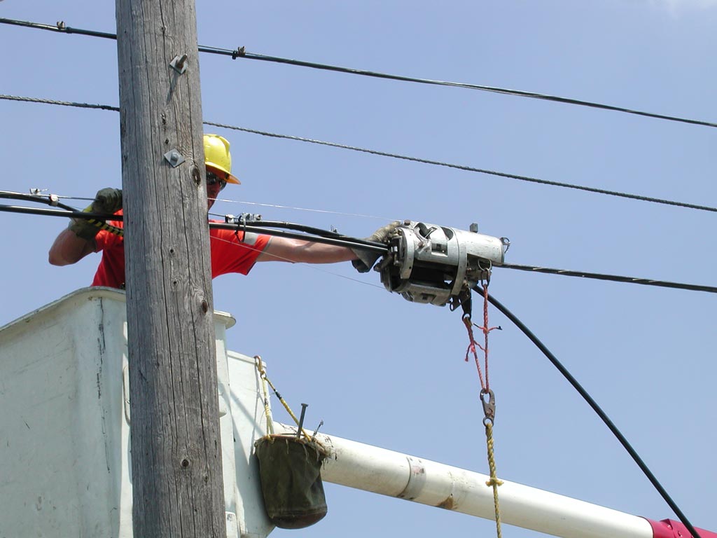
Firstly, note the installer's right hand is holding on to a stranded galvanized steel messenger wire (also called a messenger strand or cable). For this aerial installation, it is strung between utility poles (supported by a clamp attached to the bolt with the square washer you can see on this side of the utility pole), and provides support for the fibre optic cable (most communication cables are not strong enough to support themselves over the distance between utility poles).
This machine is a cable lashing machine (or lasher). These were developed by GMP Co. (the full company name is General Machine Products, though the company was founded by George M. Pfundt). It is pulled along the cable (by the rope clipped to it), and spiral-wraps two stainless alloy wires (you can see these extending from the machine towards the utility pole, where they are clamped to the messenger wire) around both the messenger wire and the cable being installed. In this case (as is common), there is already one cable installed (and already lashed to the messenger wire), and this new cable (curving down, from the right side of the lasher) is being over-lashed to that.
10 of 33

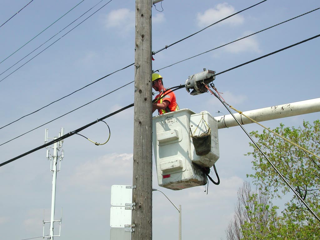

An alternative to messenger cable and lashing is to use “figure 8” cable (so-called as the cross-section looks like an “8”). This has a steel cable (the top of the 8) attached to the fibre optic cable (the bottom of the 8).
Another alternative for aerial installations is All-dielectric self-supporting (ADSS) cable. This has a hard and smooth surface (so ice can't cling to it) over a layer of Kevlar (DuPont's registered trademark for a type of aromatic polyamide fibre they developed in 1965) fibres (or yarn). These provide both strength and rodent protection. Another reason for the Kevlar not being on the surface is that it needs to be protected from the ultraviolet light from the sun, which would degrade the Kevlar.
13 of 33
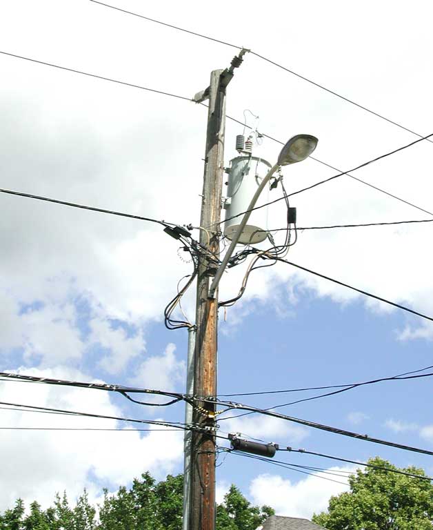
Here's a classic utility pole. This one is wood, and at the very top is the highest voltage (since it is the most dangerous). In this case, two distribution lines at 27,600 volts. One of these is supplying the pole-mounted distribution transformer (through the scary high-voltage insulator at the top). The other input to this transformer is a ground connection, which runs down the pole to a spike driven into the ground.
The transformer has a two-phase 240/120 volt output. This means that the voltage is 240 volts “phase to phase” (from one line-voltage wire to the other), and 120 volts from either line to ground. The transformer output feeds the heavier wires which are then run directly to the adjacent houses (and also down the pole to adjacent houses that have paid extra to have a buried electrical service entrance).
Generally these utility poles are owned by the local electricity distribution utility, but may also be owned by the local telephone company or municipality. In any case, whoever the owner is usually rents space on their poles for a charge that is often $20 to $40 per pole per year.
After a large safety gap, the next lower service on a utility pole is usually the local telephone company (since they have been using the poles for a long time), then below that will be the cable TV company, and below that any fibre optic cable companies. Sometimes, there are messenger wires (and cables) on both sides of a utility pole.
On this pole, below the 240/120 volt power lines, the next service is the local cable TV company (you can tell by the characteristic coaxial cable slack bend to the left of the pole – also, farther along the cable you can see the line extenders). The cable company is running their fibre optic cables lashed to the same messenger wire (you can tell by the yellow spiral wrap).
Below that is the telephone company's service (you can tell by the terminal enclosure with telephone line in-line with the 50-pair distribution cable, and the drop cables coming out from the terminal, going directly to people's homes.
14 of 33

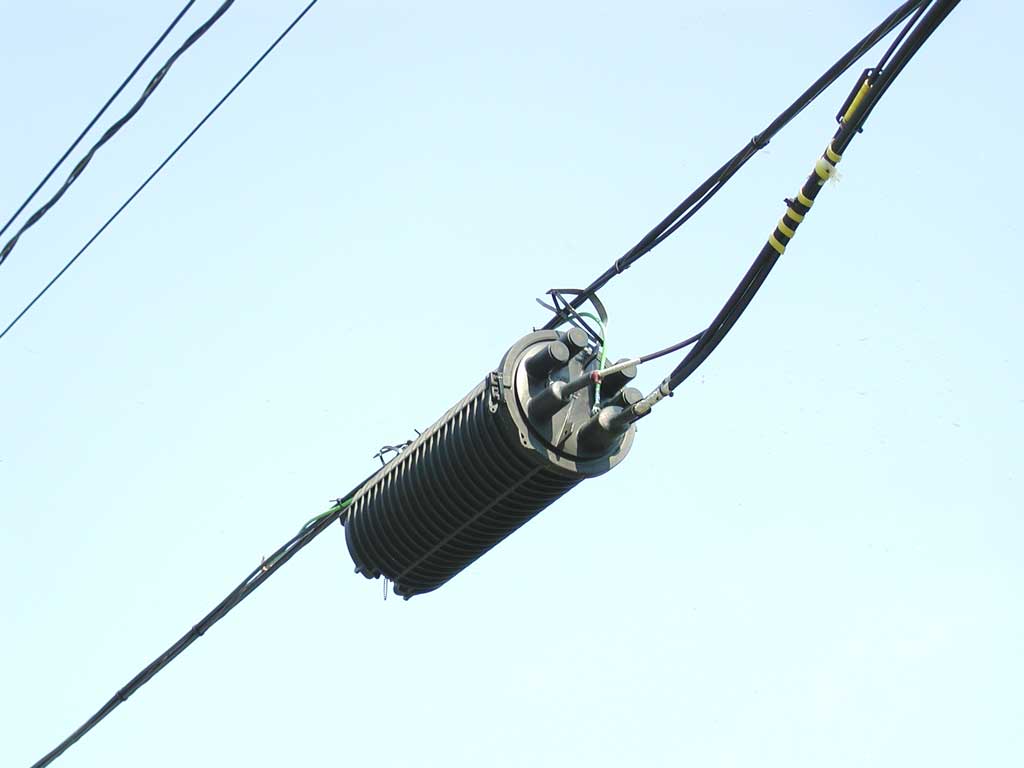
This is an aerial type, since it is lightweight and waterproof (but not airtight, so is not used in underground vaults).
Pictured is the “butt” style, since the cables enter at only one side. If cable entry is required on both sides, then an “in-line” (also called “through”) style is used. A typical closure is the 3M Fiber Aerial Terminal (some details are here, but the pictured one is a Corning Cable Systems (which used to be called Siecor) Splice Closure (read about it here).
16 of 33


Once the fibre to a field device is installed, they install a loopback jumper (they call this a glass-loop) at the end of every pair of fibre optic strands, so a technician in the central office can check the fibre at connector losses using an optical time domain reflectometer (OTDR).
The truck has a 110v generator, heating and air conditioning (you can see the unit on the roof), and inside there is a long work surface, with fluorescent lighting above it to provide even lighting.
The guard around the vault opening ensures passers-by don't fall into it.
18 of 33


Some information on a typical fusion splicer is here.
21 of 33
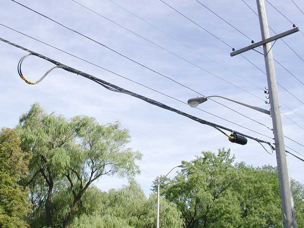
I'm sure you've noticed the loops of fibre optic cable surrounding splice closures. Here, the splice closure and the cable to the left of it are held up with cable ties. By cutting the cable ties, the splice closure can be brought down to ground level, and worked on in a splicing truck. Often these trucks have a little door in the back, just big enough for the splice closure, so they can work in a well-lit dry environment, even if it is hot, cold, rainy, or windy outside.
The loop to the right of the splice closure is one of the two cables looping back to the left, as that is where it came from.
The diagram below shows a simplified view of all this.
22 of 33
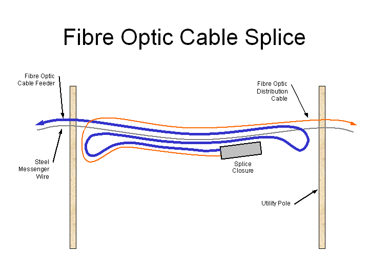
Typically, several distribution cables will exit the splice closure, and after the loop to the left (which allows the splice closure to be brought down to ground) will either continue to the right, or loop (at the right) to continue to the left.
Note that the loops must be large as outdoor fibre optic cable has a relatively large minimum bend radius (the 48-strand fibre here has a minimum bend radius of 11"). Sometimes you see a spoked frame inside the loops to ensure the bend radius isn't too small.
23 of 33


The white panel across the top is a heavy sheet metal shelf which is inserted into the slots along the sides at many heights (similar to adjusting the height of your refrigerator shelves).
26 of 33


The distribution fibres enter at the top-right, in the six clear plastic tubes, the first five tubes each have four fibres, and the sixth tube has two fibres, for a total of 22. The distribution fibres wrap counter-clockwise around the outside track to the bottom-left where the plastic tubes end, and the bare fibres enter the middle, where they wrap around a few times for slack, and are fusion spliced to the feeder fibres.
33 of 33

A page from the Superior Essex Inc. catalogue showing the ANSI/TIA/EIA-598-B colour code used for fibre strands is here.