ADSL2+ DSL Remote Concentrator
1 of 55
Well,if you've read about Outside Plant, and maybe about Rural Outside Plant, now you're ready for this story.
Used as a traditional POTS (plain old telephone service) line, with the newest, latest, V.92 dial-up modem, the fastest your telephone line can carry data is less than 56,000 bits/s. Using high-frequency signals (higher than we can hear), and a technology called DSL (digital subscriber line), the existing run of cable between the Central Office and your telephone can carry up to about 5,000,000 bits/s (5 Mbits/s) of data. Well, all these are so yesterday, because the telephone company wants to send about 20 Mbits/s of data to you (and charge accordingly) so they can also send you “Cable TV quality” television. Twisted pair copper cables, such as the telephone line to your house from the Central Office can carry signals this fast, but only for about 1 km, not the greater distance typically encountered to the Central Office.
So, we're going to talk about ADSL2+ Remote Concentrators, and how they are installed, powered, and connected to our existing telephone lines.
We'll start by noting that urban and suburban telephone customer's telephones are typically connected through up to 5 km of copper cable to their nearest Central Office.
2 of 55
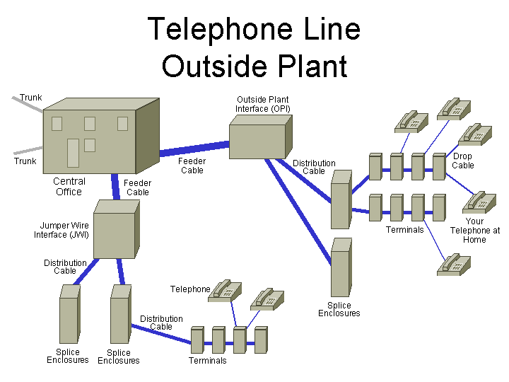
As shown here, the 5 km of cable between the Central Office and your home goes a sequence of enclosures, jumpers, splices, terminals to get to your house.
3 of 55
While fibre optic cable can carry signals as fast and far as needed, it is too expensive to run it to everyone's home, so many telephone companies are implementing an FTTH (fibre to the hub) solution. In this case, the hub is a Remote Concentrator, and it is located at an OPI or JWI, as these are generally within 1 km of people's homes. A new fibre optic cable is then only needed from the Central Office to the remote concentrator, which can then serve the few hundred customers in that immediate area.
4 of 55
So it all starts here, at a telephone company Central Office. It is already connected to other Central Offices and the Internet through fibre optic cables.
5 of 55
And here is a typical Jumper Wire Interface (JWI), this one made by Nortel Networks. It is connected to the nearest Central Office with, perhaps, a 900-pair feeder cable. And it interconnects the pairs from this cable to smaller, perhaps 200-pair, distribution cables which provide the pairs to people's homes.
You may recall that one advantage of this type of enclosure is that the back does not open, so is available for mounting a remote concentrator, and lookie, there is one there.
6 of 55
Here's another JWI, and we can see three remote concentrators mounted. Hanging these on existing cabinets removes the need for a base, allows direct cable access between the JWI and remote concentrator cabinets, and reduces the real estate needs (and provides the opportunity of getting them installed without anyone complaining about the phone company installing something ugly in the neighbourhood, and getting free use of public real estate). These are adjacent to a condominium, where the phone company is no doubt expecting many new customers.
7 of 55
Unlike this apartment building, many condominiums don't allow individuals to install satellite dishes, this is one reason why phone companies (that offer satellite TV service) are so interested in IPTV.
8 of 55
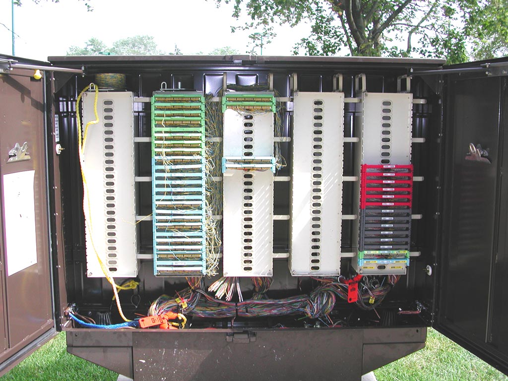
Here the JWI's doors are open. This JWI has one remote concentrator at the back-right, and the cable entrance from that is below the punch-down wafers with the red and grey retainer covers, below the right column.
9 of 55
Here's a close-up of the column of punch-downs for the remote concentrator.
The wafers with the red retainer covers are for the POTS (plain old telephone service) pairs from the Central Office. There are six of these, and each wafer terminates 25 pairs, so this is a total of 150 pairs, of which 144 are needed, as the remote concentrator has three cards that each terminate 48 telephone lines.
There are six wafers with grey retainer covers, and these are for the 144 POTS/ADSL2+ pairs to the customers.
Below that are the power pairs.
10 of 55
Here's a close-up showing the holes drilled into the back of the cabinet for the cable entrance (and the aluminum bits left from the drilling). The cable shields are all carefully grounded (the flat braided silver straps, with eyelets over the threaded nut).
On the copper pairs, you can see some of the coloured binder wraps, separating and identifying the binder groups of 25-pairs each.
The orange tag and spiral wrap identifies the fibre optic cable. Since the actual optical signal is infrared (as the fibre optic cable is most transparent to that wavelength), which is invisible to human eyes, caution is necessary (only if one was to look into the end of a “lit” fibre strand) as the light could damage one's eyes.
11 of 55
Here is a close-up of the power pairs. The green wafer (here terminating the 25 pairs numbered 1,926 through 1,950) has the power from the Central Office. The blue wafers terminate the five pairs that provide the power to the remote concentrator.
12 of 55
This is another, though older, popular type of enclosure. This one is made by 3M, and is called an Outside Plant Interface (OPI). This one has doors on the front and back, so the remote concentrator cannot be mounted on it.
13 of 55
When the remote concentrator cannot be mounted on the OPI (because it has doors on the front and back) or JWI (in this case, because there are two back-to-back – they are along the sidewalk, under the the tree), it is mounted on a concrete pad. Here there are two (they seemed to be sized to each provide enough service for one “JWI's worth“ of customers).
These concrete pads were poured in the middle of winter, and they didn't do a very workman-like job, and they aren't level.
In fact, there is some controversy between municipalities and carriers as to whether the carriers should be paying rent (or even a percentage of revenue or profits) for such use of real estate. When there was just one “phone company“, everybody considered this just another government service (nobody expects the post office to pay rent for the space used by their mail boxes), but now that there are many carriers, which are mostly private businesses, why should one carrier be allowed the free use of a public resource (this includes the use of road right-of-ways for their cables).
14 of 55
The fibre optic cable which needs to be run from the nearest Central Office to the remote concentrator may be aerial (on utility poles, or here it is buried about two-feet deep, beside a sidewalk. The black fibre optic cables are normally in the white plastic conduits, but here the conduits are being repaired.
15 of 55
This concrete pad does not yet have the remote concentrator enclosure mounted, but it does nicely show how it will be connected to the world:
- 200-pair cable, which is run to the nearby OPI.
- One fibre optic cable, run to the cable vault (below the man-hole cover).
- One six-pair copper cable, to bring the electrical power to the remote concentrator.
- One bare ground cable, for safety.
The contractor repaired the grass damaged during the concrete pad installation, and has left a helpful sign. Let's get a closer look...
16 of 55
Ah, “Please Water Me”. Maybe that didn't happen.
17 of 55
The concrete pad also has a ground cable installed (this is before the nice grass was laid).
18 of 55
This is a close-up view of the 200-pair copper cable (the thickest cable), the fibre optic cable (the thinnest black cable), the power cable, and the ground wire (barely visible coming from the smaller gray conduit behind).
19 of 55
Later, this conduit is sealed to prevent moisture (bugs, sewer gas ...) from coming up into the cabinet. The end of the unused conduit has a plastic cap inserted to seal it.
20 of 55
The copper cable is made by Superior Essex, type BKMF telephone cable, with 200 pairs (most every copper or fibre optic cable jacket indicates the number of pairs of copper, or strands of glass). The specification sheet for the cable (here) notes this particular cable has better than usual physical protection.
21 of 55
This is what the 200-pair cable looks like up close. It has a super-tough outer jacket, with an attached aluminum layer. As for most outside plant cables, it is filled (also called flooded) with a jelly (sometimes called grease filled) to keep water out, so is a sticky mess to work with. The red plastic in front is the colour-coded unit binder (you can see a black one, still spiral-wrapped in the cable) to separate and identify each 25-pair binder group.
The yellow string is a rip cord which helps the technician remove the cable jacket (they grab it with pliers, and pull it, though that probably wouldn't do too much on this particular cable jacket).
22 of 55
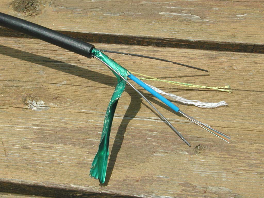
This is the thinnest cable, and is the fibre optic cable that makes this whole project work, as it carries the high-speed data.
This cable has six strands of glass. These are enclosed in the blue loose buffer tube (again, filled with gel). The cladding for each strand has a different colour, for identification.
Fibre optic cables used indoors typically require a smaller bend radius, so use a tight buffer tube. This is a protective tube extruded over the strands of glass. Due to microbendng (which is due to miniscule differences in the buffer tube thickness and concentricity), the attenuation of tight buffer tube fibre optic cables is greater, but this is not a problem for indoor cables as they are typically relatively short (under 2 km), However, outside plant cable can be much longer, so use loose tube construction, where the fibre strands are, in effect laying along the inside of a drinkng straw. Because they loosely lie inside the buffer tube, they have lower attenuation. However, since the loose buffer tube will kink (picture bendng a drinking straw too sharply), installers have to be careful not to bend the fibre optic cable too much.
The buffer tube has a thick aluminum foil protective shield, and then the cable has two very stiff spring-steel wires. These ensure that the fibre optic cable is not bent too sharply. Finally, the whole cable has a tough black plastic jacket.
You may have noticed that outdoor cables are always black, This is due to carbon black (a fine black powder made of carbon), which is added to plastic to absorb the ultraviolet light of sunlight, which would otherwide make the plastic brittle due to photo degredation.
23 of 55
Here's a close-up showing there are six strands of glass in each fibre optic cable (from bottom to top, they are white, green, orange, blue, slate, and brown). These would be single mode fibre optic cables, which mean the diameter of the coloured cladding is 125 μm (a micron is a millionth of a meter, so 125 μm is 1/8 of a millimeter), and the glass core within that cladding which actually carries the light is about 8 μm in diameter.
The strings are rip cords to help the technician remove the cable jacket and shield. In addition to rip cords, sometimes you see fine coloured threads in cables, these identify the manufacturing plant.
24 of 55
This third cable has six twisted pairs with a corrugated aluminum shield and a tough jacket. This is likely used for the five pairs that bring the power from the Central Office to the remote concentrator.
25 of 55
OK, so here we are at the remote concentrator, we've got the 200-pair cable, fibre optic cable, and power cable coming to it.
26 of 55
Here's the 200-pair cable in the OPI, ready to be punched-down to connect to the telephone lines from the Central Office and to the customers.
27 of 55
This particular remote concentrator is still being installed. It is mounted on the concrete pad, and you can see the cables ready to be terminated.
28 of 55
The sheet metal cover is not yet installed, so here you can see the cable from the OPI (coming up through the concrete pad) spliced (under the plastic bag) to cables from the remote concentrator innards.
29 of 55
Here you can see the three 100-pair cables (each with a blue, orange, or green colour-coded cable tie, to match the cabling in the cabinet) from the lightning protector blocks in the cabinet. There's a thinner black cable with the power pairs going into the cabinet too.
30 of 55
A few days later, and the installers were back. They chipped out some of the duct sealant so they could run a new fibre optic cable to the enclosure, as the first ones went to the wrong cable vault.
31 of 55
Here's the cable entry under the remote concentrator cabinet. You can see the bare ground wire in front, the “X”-shaped strengthening brace, and screen-covered ventilation holes.
32 of 55
Now the three 100-pair signal cables, and the smaller power cable is installed.
33 of 55

- One COP (Control and Optical Pack), which connects to the pair of optical fibres to the Central Office, and to a backplane to drive the LIMs. One such module that can work in this chassis has a datasheet here, and supports up to two full-duplex 1000Base-LX Ethernet interfaces (these run at 1 Gbits/s over 10 km of single mode optical fibre, at 1,310 nm) to the Central Office.
- Three LIMs (Line Interface Modules). These are the devices that take the high-speed data from the COP, and convert it to the ADSL2+ modulation to the customer (and back again, for the data from the customer). A datasheet is here. The LIM supports 48 ADSL2+ ports. The actual speed that ADSL2+ provides to end users depends on the length and type of cable, but up to 20 Mbits/s over 5,000 feet of cable is possible. One source of additional detail is here.
- Three LPM (Line Protection Modules), one paired with each LIM. These each support 48 ports, over a temperature range of -40°C to 46°C, and include the splitter which combines the POTS copper service from the Central Office with the ADSL2+ service provided by the LIM, onto the single pair to the customer. A datasheet is here.
- The chassis also protector blocks, to protect the equipment from over-voltages (such as from lightning strikes to the copper cables).
- The chassis also includes a power supply with fan unit. As described in this case study from Lucent Technologies, powering such equipment can be a big problem, and they solve it by using five (since it takes that many to carry the required current) of the existing 24-gauge copper pairs (normally used for voice) for power. More on this below.
34 of 55
Here is the Lucent Technologies Stinger DSL Access Concentrator Compact Remote in real life. Here it is mounted on the back of a JWI.
35 of 55
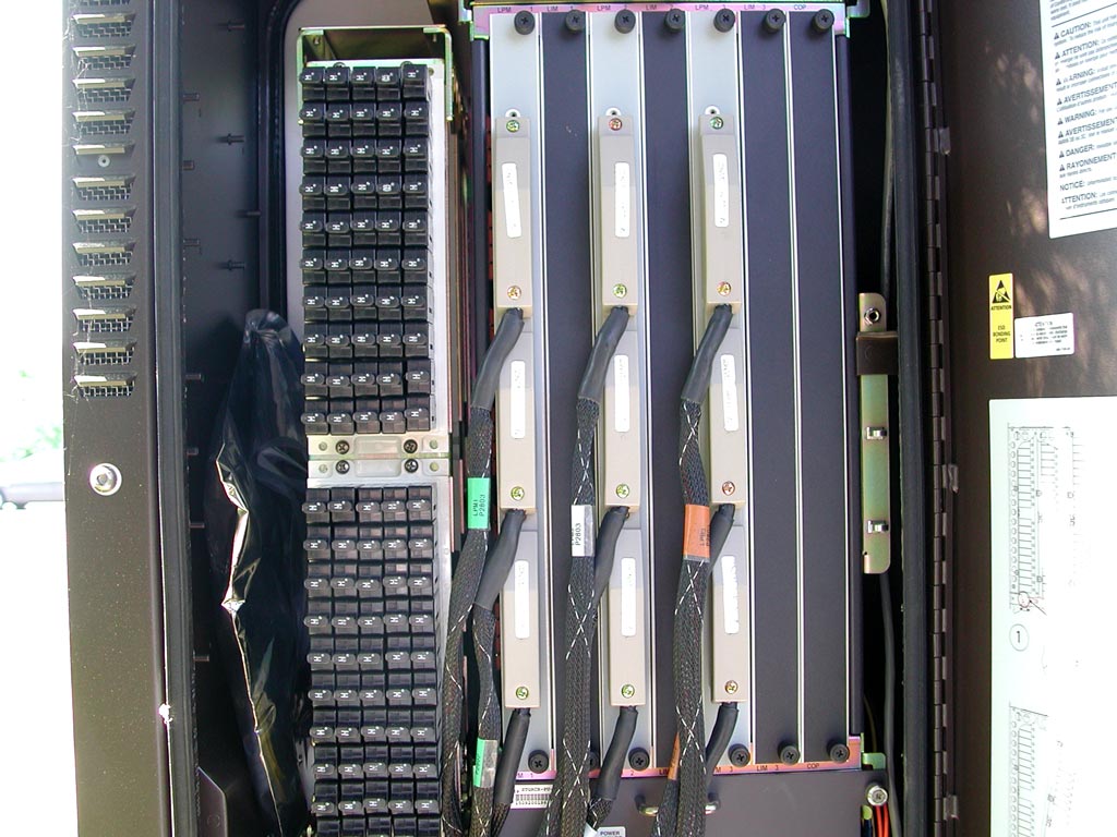
Here's a nice full-frontal view. This chassis is a masterpiece of compactness.
The fan unit is at the top, with a cable to an extra fan. On the left is the top layer of protector blocks. To the right are three LPMs. These are the vertical cards with silver front panels, and each has three Tyco 64-pin connectors (the cables have colour-coded tape, of green, white, and red), which provide a total of 96 pairs of electrical connections, as required for the 48 ports per LPM (one pair in, and one pair out per LIM port). To the right of each LIM is a card slot (here with a blank cover-plate as the LIMs are not installed) for the LPM's associated LIMs. The extreme right slot is for the COP, also not installed. At the bottom is the power supply, and below that is the fibre optic cable tray (with connectors at the right).
In September 2006, Bell Canada stated:
- They will be using Microsoft's IPTV, so need to wait for the required features to be ready, such as: sharing music and pictures among the televisions in a home, recording a television program from one television, and watch it on another in the home, providing picture-in-picture in the video stream to a single television, and fast channel changing capability. Microsoft's proprietary video compression can deliver a standard-definition video stream in 1.5 to 1.8 Mbits/s, and a high-definition video stream in 7 to 9 Mbits/s.
- They are waiting for the Alcatel/Lucent VDSL2 cards to be available. These are expected to work at up to 26 Mbits/s.
- In the last fiscal year, Bell Canada's customers cancelled 419,000 phone lines, due to competition from cable telephony, cellular telephone, Internet-based telephone service, and other factors.
- Bell Canada is spending over a billion dollars to implement this system of fibre optic cables to remove concentrators, which are within 1.2 km of its 4,300,000 customers in the corridor from Windsor to Quebec City.
- The system will enable sending two high-definition TV signals (to support two televisions watching different channels), plus high-speed Internet (plus traditional telephone) over the existing single copper pair to each customer.
36 of 55
This diagram from the inside of the door shows a side-view of the protector blocks, showing there are three layers of them, and a fancy mechansim for accessing the blocks (these plug-in modules are often damaged by lightning and need to be replaced &ndash making the ultimate sacrifice for the cause, so to speak).
37 of 55
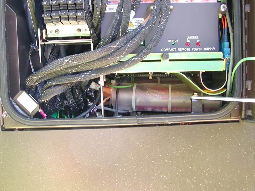
Here is the power supply, with test points so that a technician can easily measure the output voltage. You can also see some of the labelling for the plug-in card positions, which from left to right are: LPM1, LIM1, LPM2, LIM2, LPM3, LIM3, and COP.
Below the power supply is the fibre tray. This pulls out (and has a retainer screw to keep it closed). Coiled in the tray are four fibre optic strands. To the right (labelled 1 through 4) are the fibre optic connectors, with two strands of glass for each full-duplex gigabit Ethernet connector.
38 of 55
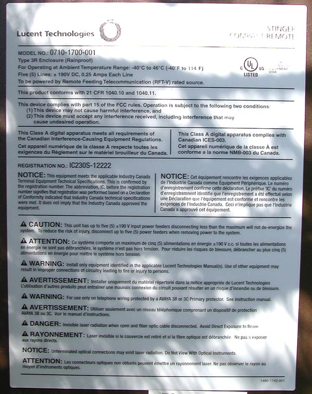
This label is on the inside of the door, and gives some detail on the power supply. It states that it is powered by five lines at ±190 volts DC, 0.25 amps each line. The datasheet here notes that each line is limited to 100 VA, and the entire chassis draws up to 260 watts.
At 0.25 A and 190 volts, each line can supply 47.5 watts, for a total of 237.5 watts for the five lines.
24-gauge copper wire has a resistance of 25.7 Ω per 1,000 feet. If the JWI was three miles (cable length) from the Central Office, that would be a round-trip loop of 5,280 feet per mile × 3 miles × 2 wires in loop = 31,600 feet of wire, which would have a resistance of 25.7 Ω × 31.6 ohms per thousand feet = 814 Ω. At 250 mA current, this length of wire would have a voltage drop of 0.25 A × 814 Ω = 204 volts. That means the power supply at the Central Office must supply 204 volts (to compensate for the voltage drop) + 190 volts (needed at the remote concentrator = 394 volts. For safety, this is likely sent at +197 volts on one wire, and -197 volts on the other wire of each pair (which is perhaps what the “±” means, and why the cabinet warning label indicates that up to 200 volts is present inside).
The label also indicates that this power must be supplied by a “Remote Feeding Telecommunication (RFT-V) rated source”, and says: “Caution: This unit has up to five ± 190 volt input power feeders. Disconnecting less than five maximum will not de-energize the system. To reduce the risk of injury, disconnect up to five power feeders when removing power to the system.”.
39 of 55
These labels were applied only after the LIMs and COP were installed. They indicate:
- The designation for this cabinet
- That the cabinet is fed by power circuit CCSNDZ103874.
- Below that indicates the designations for the four strands of fibre which connect the cabinet to the Central Office (eight strands appear to be referenced, perhaps for possible future expansion).
- This Outside-plant Subscriber Line Access Multiplexer cabinet supports 144 ADSL2+ connections, so the next line is likely the pair numbers for these.
- The last lines indicate the pair numbers for the 150 copper pairs from the Central Office (144 of these carry voice, and five carry power), and the 150 pairs to people's homes.
40 of 55
This label on the inside of the door indicates which protector blocks are wired to which pairs. Each 5 × 10 matrix has protection for 48 pairs, plus up to two of the power pairs. The layer of protector blocks closest to the front of the cabinet is for LPM3.
41 of 55
Here is the top-third of the chassis. The green LEDs at the top-right are labelled Cooling Unit Status, Internal, and External, and below that Red indicates Fault, Green indicates Active, and Blinking Green indicates Initializing.
42 of 55
This is the middle-third of the chassis. At the left are two 5 x 10 matricies of protector blocks, for a total of 100. There are three layers of these, for a total of 300. Of these, 144 (since there are three 48-port LPM/LIM card sets in the chassis) are used for POTS connections, and 144 are used for customer connections (for a total of 288 pairs). Of the remaining 12, five are used for power, and seven are unused.
So here's the part I don't understand. If 288 pairs are needed to connect this, then why is there only a 200-pair cable. Perhaps this remote concentrator taps into the existing POTS line from the CO to the customer with just a single pair (so only half of these protector blocks are used).
Anyways, a rubber gasket around the outside edge of the chassis opening ensures it is waterproof. The colour-coded tape has a numbering scheme for each connector tio ensure they are plugged-in to the correct receptacles. At the left is room for documentation, although in this case it is a fibre optic patch cord.
43 of 55
The bottom-third of the chassis shows that the wires (in the woven sleeves) from the connectors go to the back of the protector blocks, and others go below the chassis to the cabling enclosure.
At the lower-left of the chassis is a tamper switch so that it can be remotely detected when the door is opened.
Below the right side of the fibre tray is a curved guide to ensure that the fibre optic cables to the bottom of the connectors are protected, and not bent too sharply. Below the fibre tray is a translucent plastic sleeve with a BIX punch-down wafer, perhaps for the power supply pairs.
44 of 55

- A yellow Class 1 Laser warning sticker. This is for the transmitters of the two gigabit Ethernet connections, which use infrared light, so are not visible. Class 1 is the safest rating, allowing unlimited eye exposure (since the enclosure is to be installed within 10 to 15 km of a Central Office, relatively low transmit power is required).
- The two pairs of yellow-jacketed fibre optic cables are labelled “GIGE-1” and “GIGE-2”, for gigabit Ethernet 1 and 2. These provide a total of 2,000 Mbits/s of full-duplex data transfer to the Central Office. From top to bottom, the fibres are labelled 1 through 4.
- The next connector is an 8-pin modular Ethernet connection for a management interface, to support local configuration, monitoring, and testing.
- The next connector is a 9-pin DB-9 EIA-232 connector, also for a management interface (this slower interface is older, but could be used with older PCs that don't have Ethernet interfaces, or with dial-up modems).
- The next connector is a high-density DB-15 connector for alarm inputs (for example, from an over-temperature sensor, or a tamper switch).
- At the bottom are seven LED indicators, as shown a few photographs hence.
45 of 55
Here is a close-up of the top of the COP, showing the two optical transceivers, each with two LC connectors and supporting 1 Gbit/s full-duplex Ethernet to the Central Office.
46 of 55
This better shows the connectors on the COP.
47 of 55
The Ethernet interface has two LEDs, which are labelled as followws:
- L/A – Showing whether the Link Integrity Test Pulses are being received (showing that the optical receiver is properly connected through the fibre to a transmitter, usually indicated by the LED illuminating) and whether there is activity (transmitted and received data packets, indicated by the LED blinking off).
- SPD – Showing the speed of the data connection (for example illuminating green for 10 Mbits/s, or yellow to indicate 100 Mbits/s).
48 of 55
The bottom four LEDs show whether each gigabit Ethernet connection is established (that is, whether the link integrity test pulses are being received from the far end) and whether there is any data transmission or reception activity for each gigabit Ethernet connection.
49 of 55
The Control and Optics module is a STGRCR-COP-GE (Stinger Compact Remote Control and Optics module, with gigabit Ethernet interfaces to the Central Office). The Line Interface Modules each support 48 ADSL2+ connections.
50 of 55
Here's the cabinet closed. Note the warning that there is 80 to 200 volts inside, as this is the power supply voltage. The black chamfered hollow cylinder is over a ¼-turn latch to keep the door closed (there is another farther down the door). The exposed screws are all a security type. The ventilation openings all have screens to keep bugs out.
51 of 55
This is a close-up of the outside of the door latch. The 7/16" hex-head bolt is visible at the bottom.
52 of 55
Just as soon as someone makes a beautiful piece of equipment, somone else wants to save money. Here is a stamped metal version of the cabinet lock, much uglier than the machined one above.
53 of 55
This lock prevents unauthorized people from opening the cabinet.
54 of 55
Here is one style of security screw used. It is called a “clutch head” (or a “one-way slot drive”), and has a radius ground into (or cammed out of) each half of the slotted-head so that trying to undo the screw would cause the screwdriver blade to lift up. This type can be installed with a standard flat-blade screwdriver, but is extremely difficult to remove – even if you are authorized to do so.
55 of 55
Here is another style of security screw used. It has a rounded triangular (or trilobular) recessed drive. Because the opening is almost round, it looks like a rivet (hopefully preventing people from even trying to remove it).
This type requires a special screwdriver, but if you have the screwdriver, can easily be removed.
Another web site that looks at communications infrastructure is http://kramerfirm.com.


