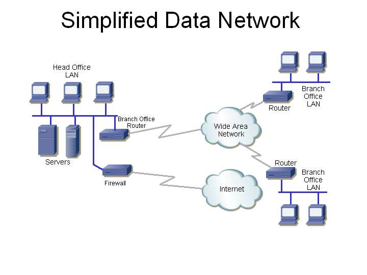
Today we're going to talk about Data Networks. Here is a simplified diagram of the data data network. It includes the following:
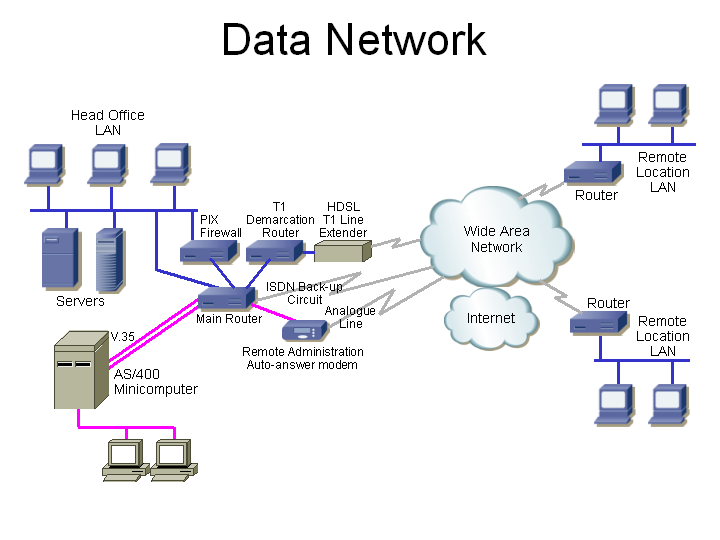
In actual fact, the above network is a bit more complicated, and has the following:
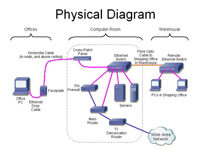
Here is how the cabling actually runs. Starting at the left, a typical office PC has a flexible UTP (unshielded twisted pair) drop cable that connects its Ethernet card to a faceplate, which is connected to the horizontal cabling which runs up the wall, and above the ceiling to the computer room. In the computer room, the cable terminates onto the back of a cross-patch panel. The cross-patch panel has a field of 48 RJ-45 receptacles, each connecting to a different office. A patch cable then connects each cross-patch panel RJ-45 to an Ethernet switch port.
All servers and routers also connect to the Ethernet switch.
Because the shipping office is more than 100 meters away, two strands of fibre optic cable run from the computer room to a remote concentrator located at the shipping office, which then has standard UTP cables to the PC there.
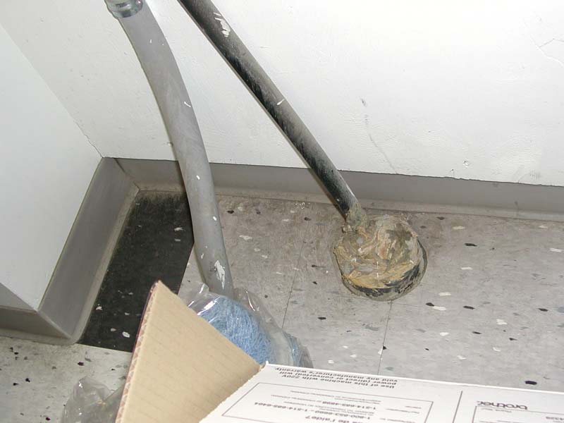
(We're looking down at a tile floor) It all starts with this — the service entrance. On the right is a black 100-pair cable coming up through the poured concrete floor, through a 5" conduit (with the extra space around the cable filled-in).

The black cable then goes up into a SIECOR (now owned by Corning Cable Systems) QTPET-100-HPFL Building Entrance Terminal (100-pair, high powered fuselink series, hence the name) over-voltage and over-current protection device (the beige metal box). This has lightning arrestors and fuses, to protect both equipment and workers for damage due to lightning or accidental contact with power cabling.

The cable comes up out of the bulding termination box (on the left) and to the phone company demarcation point. This is the BIX punch-down to the right. The sheet of paper above the termination lists the function of each pair of cables. Some are T1 (here called Megaroute by Bell Canada), some are analogue phone lines (here called 1FL by Bell Canada). Most sites aren't this organized to have the pairs clearly documented.
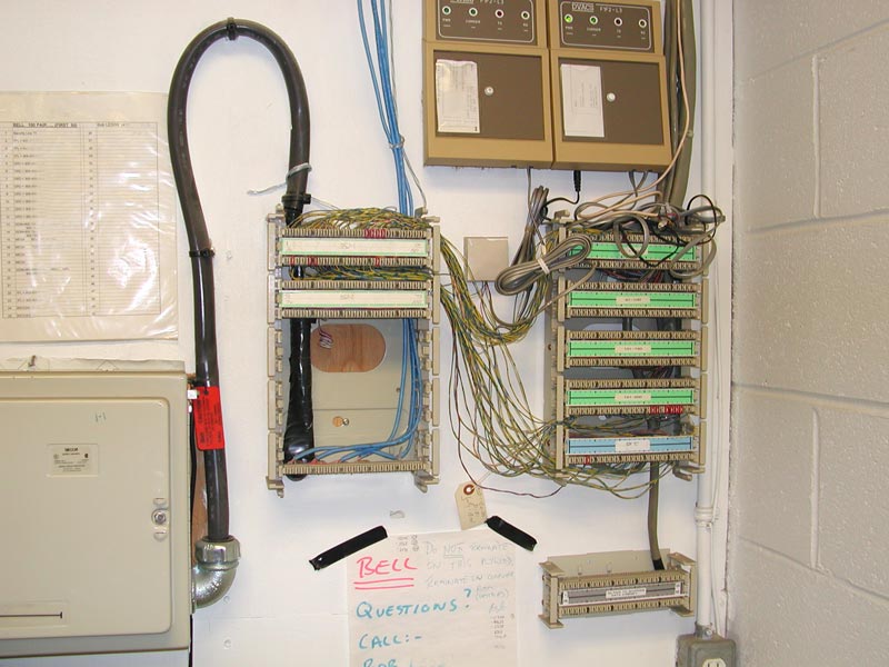
The punch-down in the middle is called the demarc (as in demarcation point), as it is the end or boundary of the ownership of the copper pairs from the phone company, and the rest of the in-house cabling is owned by the customer, and is the customer's responsibility. The writing on the white, green, and blue cards may identify the function of the pairs.
Before we continue, let's take a short detour to talk about punch-down blocks.
Firstly, all this equipment is screwed to a plywood backboard (here painted white).
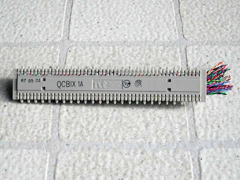
This is called a BIX wafer, and is an example of a punch-down block (the metal frame in the previous picture can hold up to 10 of these). Punch-down blocks use an insulation displacement connector (IDC) which means that to make the electrical connection, the insulation is moved (displaced) by the connector (so the installer doesn't have to first strip the insulation from wire) when the wire is forced into the connector with a punch-down tool which the installer hits with the palm of his hand. A common old type of punch-down was called a "66-block" (these required more wall space, and are not suited to high-frequency signals), other new systems are 110 (originally developed by AT&) or Krone (now owned by ADC Telecommunications). Punch-down blocks can only be used for solid-conductor wire. Stranded wire (where each conductor is comprised of many smaller-gauge copper strands) is slightly more expensive, and is used when the cable needs to be flexible.

BIX (Building Industry Cross-connect) is part of the IBDN (Integrated Building Distribution Network) which was initially designed by Nortel Networks (which used to call themselves Northern Telecom), but this group was sold to CDT (Cable Design Technologies, and called Nordx/CDT), and later Belden bought the whole lot. This BIX wafer terminates 25 pairs (50 wires). Here the 25 pairs are punched-down to one side of the wafer (a knife on the punch-down tool has trimmed off any wire which extended below the wafer). This wafer is then inserted into the metal frame (it clicks in) with the punched-down side against the wall, so you only see the unused side.

Here's a whopper of a close-up of just the left side of a BIX wafer. The white wire (with blue stripe) at the left is punched into the first position. The metal contact in this position is connected to another metal contact at the far side (which doesn't yet have a wire punched-down). The blue wire (with white stripe) beside that (this is the other half of pair 1) is punched into the second position, which is electrically connected to the second position on the far side of the wafer, and so on.

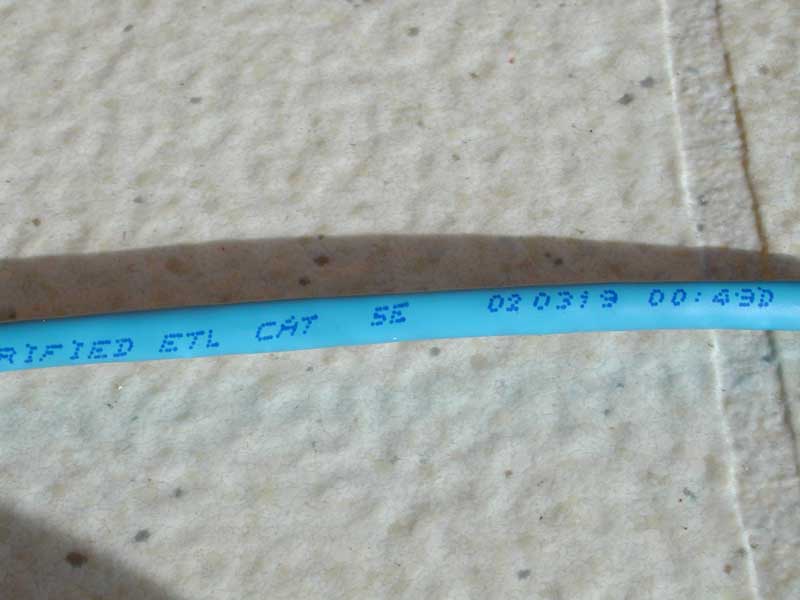
There are several standards for building cabling. Electrical specifications are developed by the Telecommunications Industry Association in TIA-568 – Commercial Building Wiring Standard. A Category system is used to specify the requirements and capability of cabling systems. Unshielded Twisted Pair (UTP) cabling (that is, the each pair of wires is twisted together, and these are all enclosed by a jacket, with no shielding) is usually used for copper cabling within buildings, for example, for voice, T1, ISDN, and Ethernet connections. Enhanced Category 5 cable (usually called Category 5e) is the minimum used for new installations, as it can carry 100 Mbit/s Ethernet traffic (or voice, T1, ISDN and other signals as well) a distance of 100 metres. Category 6 cable has even better performance, and is sometimes used (it looks pretty much the same).
The conductors are always copper, and for UTP cables up to Category 5e, and use 24 gauge (0.5 mm diameter) conductors which are insulated with plastic (often coloured, to identify the wire). A pair of wires are twisted together, and is used to carry a signal (such as the data transmitted by a computer). A UTP cable is four pairs (each typically with a different twist pitch, to reduce crosstalk between the pairs), with an overall plastic jacket. The colour code often used for the pairs is as follows:
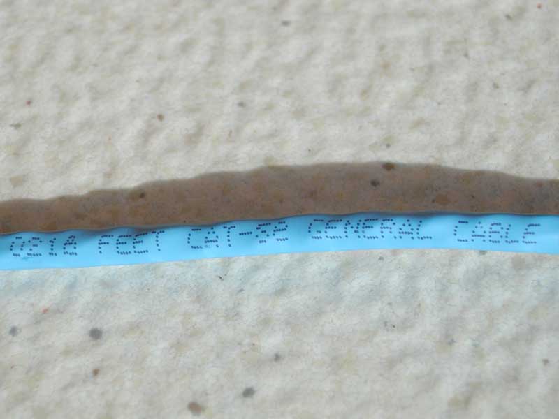
All UTP cables look somewhat the same, so you need to read the jacket (or use some really expensive test equipment) to know what type you have. The cable jackets are sometimes different colours. Organizations might use different colour jackets to identify different uses (voice or data, secure or unsecure) or cable grades (category 5e or category 6).

That's the end of our punch-down and cabling detour, now back to our regularly scheduled photo essay.
So we have the phone company demarc on the left, and the beginning of the in-house cabling on the right. Between the left and right punch-downs are yellow and blue cross-patch pairs. These are punched-down to the front of each BIX block, and as you can see there are less than 40 pairs actually used. These barely-twisted cross-patch pairs carry all the voice and data communication for the whole company which has a 250,000 square foot warehouse at this location, and about four remote locations, with 260 employees in all. The pairs are used for the following:
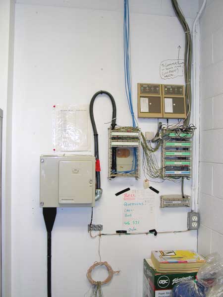
Before we go upstairs, let's take a step back. The 200-pair black cable comes in from the phone company from the bottom left, and a 200-pair grey cable goes up at the right, to the computer room (the voice PBX is also located there) upstairs.
This building is in an industrial park, with a low density of customers, and these have traditional communication requirements which only require copper cabling. In an urban area, an office building would have a high density of customers, many typically needing high-speed communications. Such buildings would have fibre optic cables going to a phone company owned ATM switch, typically located in the basement. Adapters in this ATM edge device would provide the T1, analogue telephone line, and other copper connections needed by the tenants.
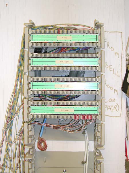
Here we are upstairs in the computer room. The 200-pair grey cable comes through the wall, is coiled behind the BIX wafers, and the pairs are all punched-down onto the back contacts of these eight BIX wafers. The two white 4-pair cables going down at the bottom right are the T1s. One cable has the T1 (each T1 uses one pair for transmit, and another for the receive) used for LAN data (only two of the four pairs are used). The other cable has two voice T1s. The voice side of this installation is further presented here.
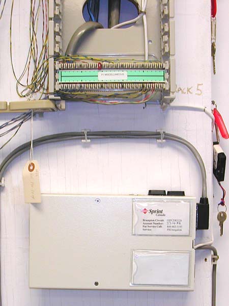
The white data T1 cable goes down, and into the opening in the wall and down ...
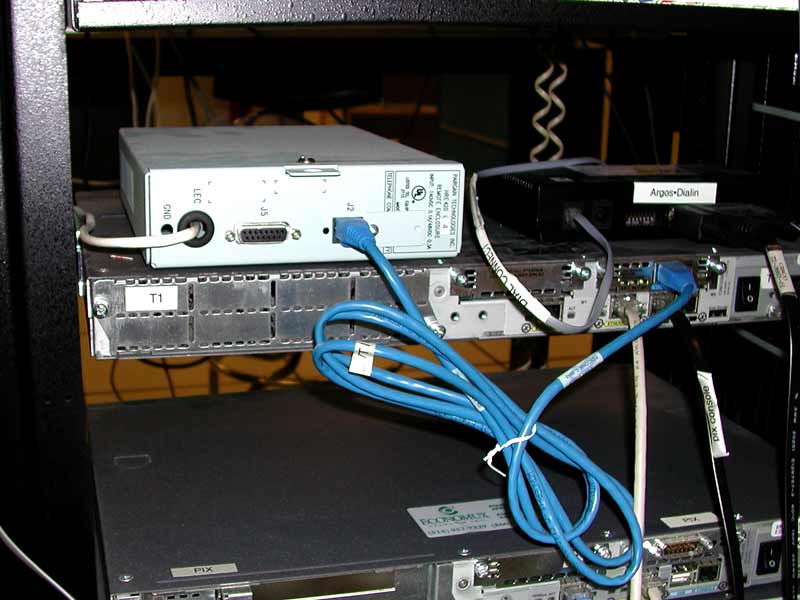
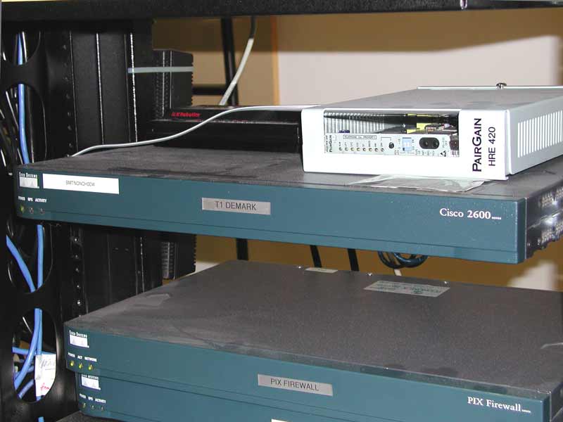
And after going under the raised computer room floor, pops out and into the light-coloured box here. This enclosure has a PairGain (now owned by ADC Telecommunications) HDSL line extender, and is required since this location is too far from the telephone company's nearest CO (central office). The blue RJ-45 cable then goes to the T1 interface on the Cisco 2600 router below the line extender (Cisco Systems is the world's largest manufacturer of routers, and has more market share in most market segments than all of its competitors combined, so when people talk about routers, it is usually a Cisco router).
For your reference, you can click see the Simplified, Detailed, and Physical diagrams (and click on your browser's “Back” button to get back here.
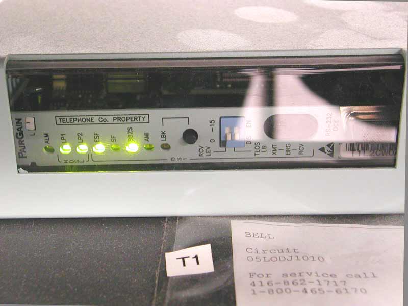
Here's the front panel of the HDSL line extender. It is a PairGain (now owned by ADC Telecommunications, Inc.) HRU-402, List 1 (some information is here). The “L1&rdquo means this model can be powered from either a local -48v DC power supply, or over the HDSL line pairs (which is how this one is configured). The front-panel RS-232 “craft port” (at the right) can be used to adjust its operation, though this would usually be done remotely from the CO.
Stepping back, we see that the Cisco router which is below the T1 line extender (which is in an HRE 420 enclosure) has a very simple front panel – has only three LEDs:
The black box (with the red LEDs) to the left of the PairGain HDSL line extender is an auto-answer modem, so the router can be remotely managed. Cisco routers have an RS-232 port for this purpose.
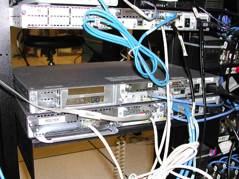
Here's the interesting side of the Cisco routers. The top Cisco 2600 router (here called the T1 Demarcation) has:
Next is the main router, it is the bottom one of the three. The T1 (white cable near the middle) is the connection to the WAN for remote site communication and public Internet access. The flat silver cable is an ISDN connection used as a back-up if the main T1 is not working. (Man, this is getting confusing, click here to see that network diagram again.) This router then provides the following client-side connections:
Finally, the middle of these three devices is a Cisco PIX firewall. This is often called an appliance firewall since the platform is a box without a keyboard or hard disk (rather than a PC running Windows, Linux or some other standard operating system). This firewall is only using two ports:
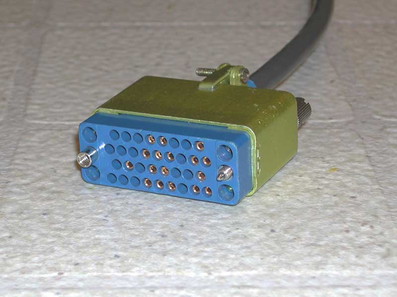
Here is a V.35 connector. It is very common for T1 connections, such as from a CSU/DSU to a router, or in this case, from the router to an AS/400.
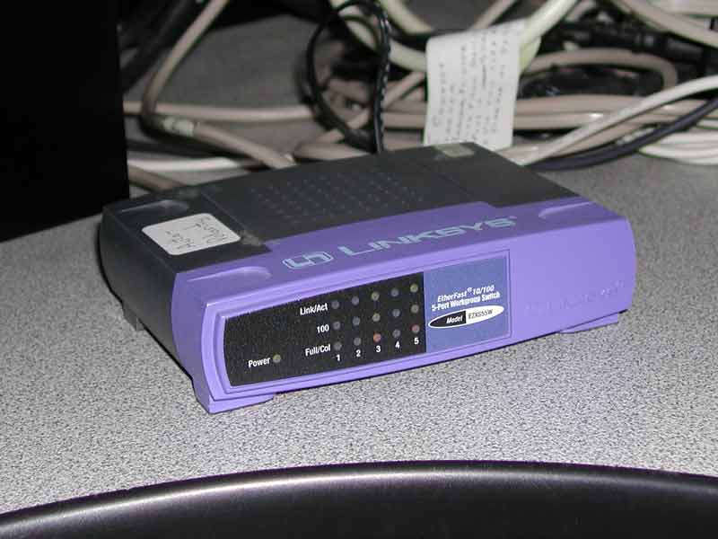
So now we need to connect to the LAN. A Local Area Network is high-speed (often 100,000,000 bits/s) communications to all the PCs, servers, routers, and printers in an organization. This is usually accomplished by connecting the Ethernet ports of these devices to an Ethernet switch. In a home or small office network a low-cost Ethernet switch or hub such as this is often used. This one is made by Linksys, which is a very large manufacturer of consumer and small business networking equipment. Linksys was bought by Cisco Systems in 2003).
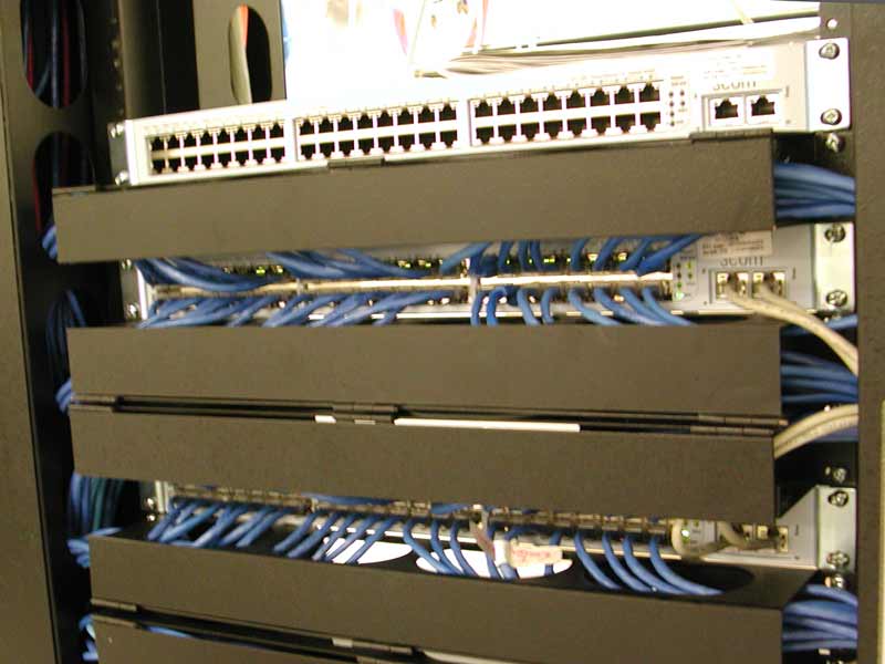
But for enterprise (a fancy networking word meaning larger) networks, you need more ports (and lots of other features, such as remote management, network monitoring, fibre optic cable connections, redundant power supplies ...). This top device is an enterprise Ethernet switch (this one is made by 3Com). It has 48 ports (six banks of eight RJ-45 receptacles) to connect to user devices (such as PCs and servers), plus two more ports (at the right) to connect to other Ethernet switches. This one is a standby switch, to be used if any of the others stop working. The switches below that have most of their ports used (blue cables connect to each of their RJ-45 receptacles), and those cables (mostly behind hinged doors to keep things neat) go to another field of RJ-45 receptacles which go to people's offices.
These switches are interconnected with a short proprietary cable (the white one, which has connectors specific to 3Com's switches) to both transfer data between the switches, and so that all switches in a stack can be administered as if it was one larger switch.
The orange cables at the top of the top switch are two pairs of fibre optic cables connecting to two similar switches hundreds of feet away (which too far for UTP cabling). The fibre optic ports are provided by proprietary (specific to this vendor) plug-in module. The lower switch has a copper plug-in module, which could be used to provide a gigabit Ethernet connection to an organization's core network.
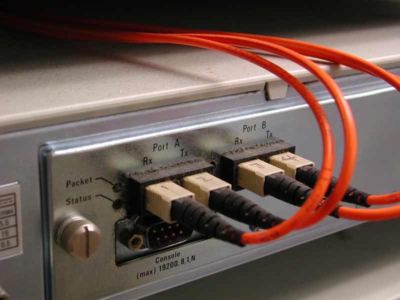
Here's a close-up of the fibre optic cable connectors. These are SC (Subscriber Connector) fibre optic connectors, which are mated by clicking them into place (no need to rotate the connector as with previous types, so these connectors can be mounted closer together). Each SC connects a single strand of glass, so two (one for transmit, the other for receive) are used for each remote device.
Here are the links to the Simplified, Detailed, and Physical diagrams (click on your browser's “Back” button to get back here.
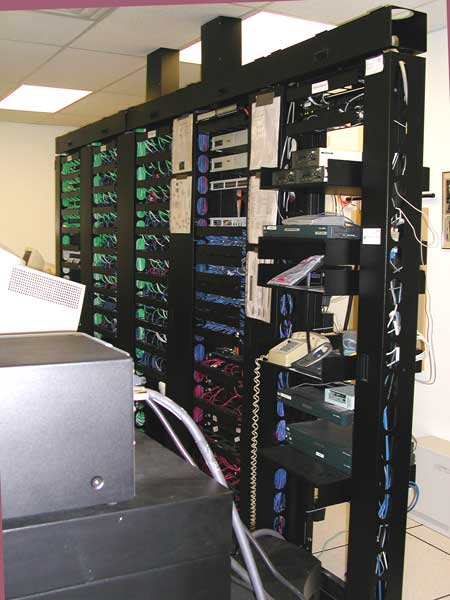
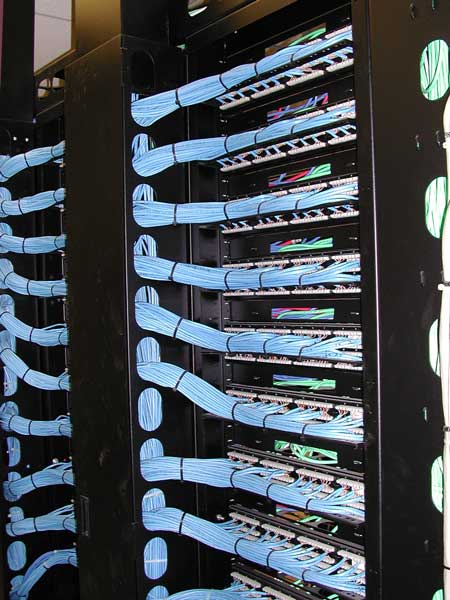
Here are five bays of 19" equipment racks (these each have two vertical rails which are 19" apart, and have threaded holes for screws used to mount equipment). The first bay of equipment is the routers, modems and other WAN equipment. The next bay is the LAN equipment, such as the Ethernet switches, as shown above. The last bay (on the left) has the voice ports to the PBX. The two closer bays are the RJ-45s which connect through horizontal building cabling to RJ-45 connectors in the offices. Cross-patch cables (mostly routed behind hinged doors) connect all the Ethernet and PBX RJ-45 receptacles (from the outer two bays) to the office RJ-45 receptacles (the centre two bays).
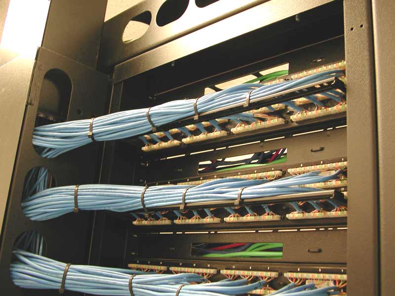
Here's the back of one of the office bays of RJ-45 receptacles, showing the UTP cabling punched-down to the back of the office RJ-45 receptacles.
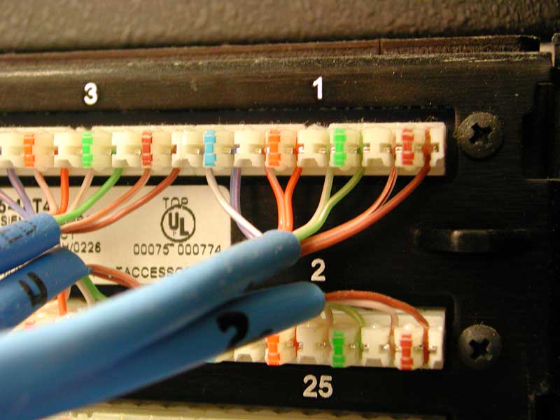
Definately four copper pairs per RJ-45. For higher-speed Ethernet (such as 100 Mbits/s) a pair is not supposed to be untwisted more than ½".
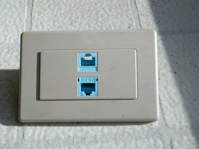
The horizontal cabling goes from the cross-patch panel in the computer room to a RJ-45 receptacle in the offices, such as this.
All these UTP cables then go from the back of the cross-patch panel, to receptacles in offices, and as well as the routers and servers in the computer room.
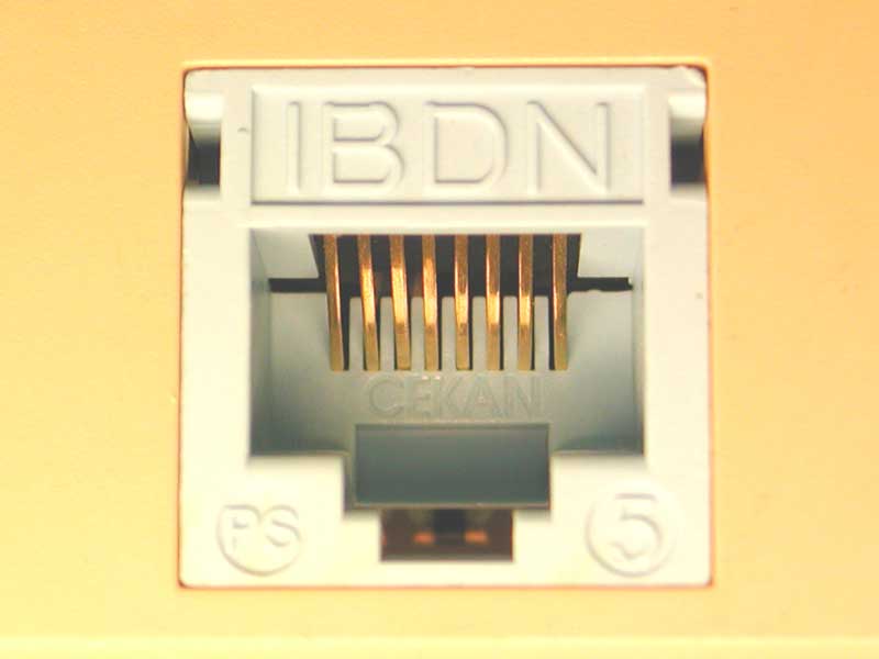
Here's a really close look at an RJ-45 (Registered Jack 45). Pin 1 is at the top-left, and pin 8 is at the top-right. As you can see, it has eight gold-plated electrical connections, for the four pairs of conductors in a UTP cable. An RJ-45 is a low-cost, reliable connector used for many purposes, such as Ethernet, ISDN, and T1. The similar, but narrower 6-pin version used by your home telephone is called an RJ-11. While gold is not as good a conductor as copper, gold does not oxidize in typical office environments, so is better than copper and most other metals in applications when exposure to air is required — such as connector contacts.
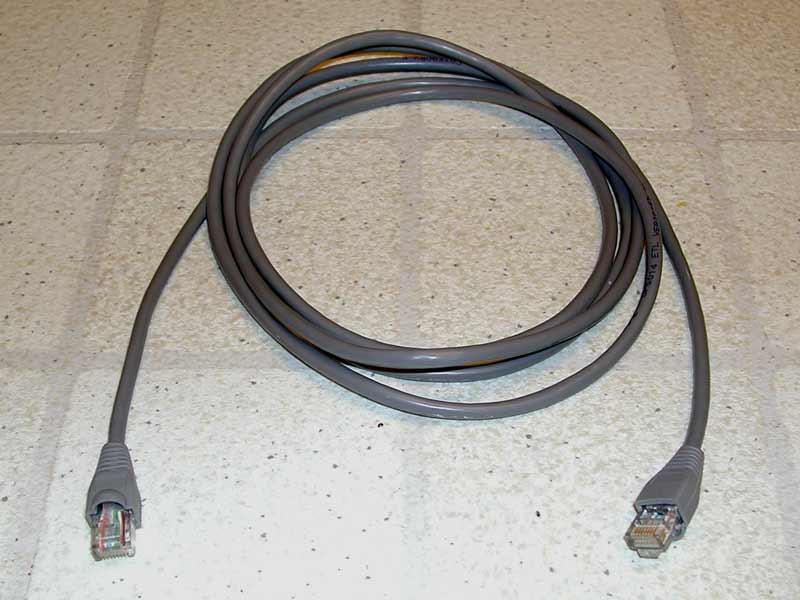
This is a UTP patch cord (or drop cable). It uses stranded-conductor cabling, which is more flexible than the solid conductor cable used for horizontal cabling. This connects the wall jack to the back of PCs, servers and routers.
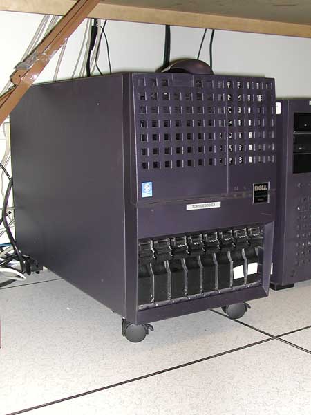
Here's typical server, though larger installations may have the guts of a server on a single board, and many of these boards would plug into a chassis a bit bigger than this. A server is typically just a PC with more memory or disk space, redundant power supplies and fans, and remote monitoring tools for temperature and other important measurements.

The drop cable plugs into the PC's Ethernet adapter, which for twisted pair cabling, uses an RJ-45 connector. On desktop PCs, this is usually beside the USB connector, near the speaker and microphone connectors. On laptop PCs it is on one of the sides or at the back.
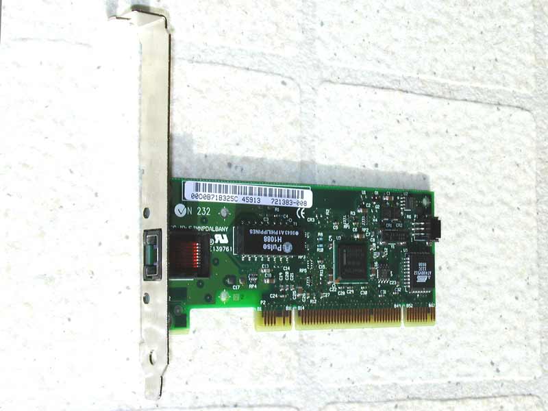
For desktop PCs, the Ethernet interface may be implemented on the motherboard (along with the main processor, memory and other basic parts of the PC), or it may be an add-in card, which some people call a NIC (network interface card). Here is a typical NIC. LEDs, visible through the holes adjacent to the RJ-45 connector often are used as follows:
So there you have it. All the way from the service entrance, through to the Ethernet adapter in a PC, what the actual boxes and cables look like for a typical LAN.